In Part 1 of this article, we talked about the preparation required for successfully hosting a percussion camp. Now let’s talk about how to promote it, and what you need to do the day of the event, and afterwards.
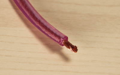
Launching a Marketing Campaign
Here are a few tips for creating an effective marketing campaign for your event. Bear in mind that promotion can be costly, even when done strictly on a local level, so know what you are getting into:
Fliers and posters – These can be produced inexpensively at any copy center. Ask local businesses – especially music stores – to place them prominently in high traffic areas.
Local advertising – If budget allows, create a print and/or electronic ad (if you have permission to do so, include the school logo in the ad) and run it several times: ideally, two months prior, one month prior, and again one week prior to your event. Target the media where you run the ad: the state music education magazine, for example, might be a good place to start, although such publications may require extended lead time (contact them well in advance to obtain their advertising schedules). Use a consistent message in all advertising to maximize retention.
Website – If you already have a website, create a special place on it to advertise your camp. (If you don’t, what are you waiting for?) Use your school’s website for this too, if you are allowed.
Social media – Create an event on Facebook. Use your social media profiles to send out your message, then repost and re-share regularly. Use hashtags sparingly.
Press release – Write a press release and send it to the education editor or city desk of your local newspapers, your state music educator publications and any other appropriate regional newsletters. Provide a photo of a previous year’s camp, or of a featured clinician at the upcoming event. Be sure to follow up with a phone call or email and invite the media to cover the event.
Promotional packet – Produce a packet of materials with the following components and send it to local area band directors (it can also be included with the press release sent to media). The packet should be mailed out at least six weeks before school breaks to allow educators, parents and students adequate time to plan their schedules.
Cover letter
Details about the camp clinician(s)
School educational philosophy
Camp flier
Registration form with photo release (must be signed by parents if the attendee is under 18 years of age)
Directions to the site of the event
Brief your staff – It is important that each member of your staff be knowledgeable about the details of the upcoming event. There is nothing more deflating to a potential participant than to hear, “I don’t know anything about the camp. You’ll have to talk to ‘so and so’.” If your staff does not care about the event, how can you expect other people to get excited about it? An informed staff member can answer questions promptly and encourage potential students they speak with to participate.
Some Additional Suggestions for Making Your Camp a Day to Remember
Drawings – Hold a drawing for a prize at the end of the day. A new instrument or accessory product such as sticks or mallets is always a crowd-pleaser. Use numbered tickets and distribute them to participants as they register.
Have a contest – This can come in the form of a percussion-related question and answer session, with accessories or in-store coupons from local music dealers for prizes.
Giveaways – Every participant should receive a memento of the event. This is the perfect way to distribute a promotional item made specifically for your store or organization.
The Day of the Event
Okay, the big day is finally here! What do you need to do now?
Plan to be on site from several hours before the start of the event to several hours afterwards. The importance of being hands-on and immediately available cannot be understated!
Expect the unexpected. As the saying goes, “Whatever can happen, will happen.” Be flexible and ready to deal with a wide range of issues.
If you don’t already have complete permissions to use photos taken at the camp – including getting parent approval for students under the age of 18 years old – make sure you get all remaining paperwork signed during the event.
Stick to the schedule. Things rarely end early, so be prepared to diplomatically move events along so that none of your attendees is shortchanged. As an example, here’s a sample schedule for a two-day event:
DAY ONE 8:00-9:00 Registration 9:00-9:10 Welcome and introductions 9:10-10:30 Clinic for all attendees 10:30 Break 10:40-12:00 Individual auditions; staff teaches essential exercises to attendees 12:00-1:00 Lunch 1:00-3:00 Sectionals (“ability” groups) 3:00-3:10 Break 3:10-5:00 Sectionals/Full Ensemble as needed
DAY TWO 9:00-9:45 Full Ensemble clinic/rehearsal 9:45-12:00 Sectionals – include one break at discretion of instructor 12:00-1:00 Lunch 1:00-1:30 Full Ensemble clinic/rehearsal 1:30-3:00 Sectionals 3:00-3:15 Break 3:15-4:00 Full Ensemble: prepare for performance 4:00-5:00 Performance for parents, friends, families. Immediately prior to the performance, talk briefly to the audience about the school music program, the camp, the importance of music education, etc. Then introduce each staff member, who will take their section/group through whatever it is that they can play comfortably. 5:00 Dismissal
What to Do Post-Camp
First, take a little time to enjoy your success. Then do the following:
Send your favorite photos from the camp to local media. Action photos of students playing percussion instruments are always of interest.
Contact members of the media (especially those who attended) to see if they need any more materials or information. If they are undecided about writing an article about the camp, your actions may push them to do so.
Contact any music manufacturers or local music stores you dealt with and offer a brief report on your camp.
Send a hand-written thank-you note to the clinicians and staff. There’s no better way to encourage their return for future events!
Talk to your staff and volunteers who worked at the camp. Ask them what worked – and what didn’t. Make a list of the things that went right and the things that went wrong. This will allow you to take steps for making your camp better next time around.
Have a great event! And remember, it’s never too early to start thinking about next year’s camp. . .
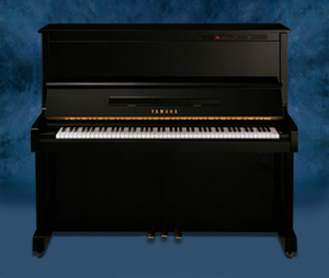
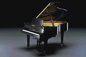
The strings of a piano are stretched under tremendous tension — from 16 to 20 tons altogether — so an extremely strong and stable frame is required to withstand the stress. Modern frames are made of cast metal, and are essential in sustaining the brilliance and beauty of notes played on the piano. The frame is such an important part that can be termed the “cornerstone” of the piano.
There is a story that a certain motorcycle manufacturer was trying to develop the ideal cast metal material for the cylinders of an engine. In the end, for some reason, it turned out to have the same composition as the cast metal in a piano frame.
So then, does the similarity lie in the fact that they are both devices that make loud sounds? No, it’s something different. If the only function of a piano frame was to support the tension of the strings, being strong and sturdy would be enough. But the frame also affects the sound by transmitting the vibrations of the strings, so it must also be elastic enough to vibrate a certain amount itself. In other words, the properties a frame must have are contradictory, namely, that the exterior be hard while the interior is somewhat soft.
The same applies to the cylinders in motorcycle engines. They must be strong enough to withstand the intense friction of the pistons, but at the same time, they need to have sufficient flexibility to cope with the heat deformation that results from the combustion of gasoline at high temperatures. Because they share these requirements, the conditions that the ideal material must meet are the same. This is the real reason why the composition of the metal castings of piano frames and motorcycle engine cylinders are similar.
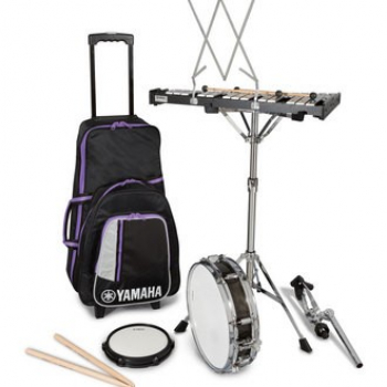
You’ve decided that you want to host a percussion camp. After all, many school music programs are in need of expert percussion instruction to prepare for parades, halftime shows and other marching band activities. You think maybe a one- or two-day event would be just right.
Now what?
If you haven’t led an event like this before, you may not be certain how to begin planning to ensure that all goes smoothly. Done correctly, a percussion camp can be an unforgettable experience that provides top-notch instruction to the attendees while bolstering the relationships between local percussion educators and artists.
So where do you start?
Set a Goal
The first step is to define what you want the camp to accomplish. Ask these important questions:
What is the criteria for attendance?
How many students should attend? Is my goal to accommodate 25, 50 or 100 attendees?
Do I need to break even on the camp fees/costs, or can I afford to lose money on it? Does money exist in a budget somewhere to support this?
Will this provide students an opportunity to learn from someone new? (i.e., someone who is not usually accessible to them.)
Write down your answers with specific details. For example, one clinic might be structured like this:
Attendance will be open to local high school students in drum corps and/or marching bands who are looking to improve their competition technique.
Each student will receive a box lunch and a T-shirt.
We need a minimum of 20 students to break even on a one-day event, or 30 students to break even on a two-day event.
We can physically accommodate up to 50 students.
The students will learn from top notch DCI instructors – people I already know and with whom I have a relationship.
Once you determine these elements, you can begin planning.
Before the Event
1. Recruit a team and identify the “go-to” people. Decide who will be in charge overall (this might well be you!), and who will be responsible for specific items, such as:
Looking after the clinicians.
Ordering and distributing food.
Making payments.
Coordinating marketing and promotion.
Hold those people accountable with clear directions and due dates on their tasks.
2. Establish a date for your camp. Pick a date that works best for the schools in your area and be sure to avoid conflicts with other regional events that may attract the same audience (i.e. marching festivals, band camps, Super Bowl™, local elections, truck/tractor pulls, etc.).
3. Locate and secure the venue for the camp, such as a high school or college campus. With the help of an onsite coordinator, ensure availability and access – who has the key? Be sure to get all necessary approvals from your school or district administrator, and identify all specific facilities that may be required, such as:
An auditorium and or band room.
Multiple rooms for percussion sectionals, each large enough to handle a small ensemble (i.e. choir room, multipurpose room, cafeteria, etc.).
Shaded outdoor rehearsal areas, especially during the summertime.
A large outdoor area for full ensemble rehearsal and performance, as well as a sizable indoor area in case of inclement weather.
4. Choose and confirm key clinicians and any additional instructors:
Get approval in writing from all clinicians and staff for the payment amount, the time frame allotted, hotel needs and those expenses that will be covered.
Recruit local percussion instructors to assist at the camp. I suggest planning on one instructor for each section: snares, tenors, bass drums, cymbals, and pit, and one for every 8-12 students. These instructors will most likely encourage their students to attend, thus increasing enrollment.
5. Launch a local marketing campaign with fliers, advertisements, press releases, social media announcements and other activities. This is such an important topic, we’ll be addressing it in detail in Part II.
6. Make arrangements to ensure the availability of all necessary instruments for the students and instructors to use.
7. Follow up regularly with local band directors, area instructors, etc. to confirm the number of students that will be attending.
8. Create a list of registered students, their instrument and ability level. This will help organize ensemble and sectional rehearsals, and allow the check-in process to proceed smoothly. The more quickly students are separated into skill levels, the better.
9. Prepare a camp packet for each student (a band folder provided by the school or a local music dealer can work well). The packet should consist of the following:
Music book(s).
Schedule of each day’s events.
Clinician biographies.
Organization literature.
A Certificate of Completion personalized for every student (given out at the conclusion of the event).
You might also consider including a T-shirt if budget allows.
Final Pre-Event Checklist
Clinician housing and travel arrangements; attendees housing (if needed).
Camp packets assembled in band folders (includes books, schedule, etc.).
All instruments tuned and in playable condition.
Stage area set up as per clinician specifications.
A device for music playback.
All necessary sound reinforcement equipment.
Music stands.
Blackboard(s) with chalk.
Amplified metronome(s).
Additional help (i.e., ushers, hosts, runners, security).
A photographer.
Water coolers, cups and refreshments, especially on hot days.
First aid kit.
A game plan for inclement weather.
Suggested Timeline
5-6 months out:
Set camp dates.
Secure clinicians.
Secure facilities with school approval.
Appoint overall camp coordinator and on-site camp coordinator.
4-5 months out:
Create materials for promotional packet.
Mail promotional packet to area schools, etc.
Deliver an event poster to area schools, etc.
3-4 months out:
Send a press release to local media.
Schedule local advertising.
2 months out:
Run local advertising.
Follow up with local area band directors.
Send an email to all registrants promoting the event.
1 month out:
Send a reminder email to all registrants again.
Run local advertising again.
1 week out:
Confirm clinicians’ travel schedule.
The day before:
Do an initial tuning and then fine-tune every day of the camp.
Allow time to assemble the percussion carriers and set up the stands.
Be sure to check out Part 2 for details on how to put together an effective marketing campaign for your percussion camp, as well as what to do during and after the event itself.
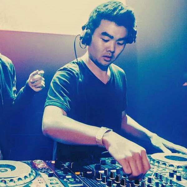
I’m Sean Tokuyama and my boss refers to me as “the new guy” at Yamaha, which is accurate, so I can’t blame him.
Who Exactly am I and Why am I Here?
I’m 26 years old and I was born and raised in Newport Beach, California, but my heart is in Los Angeles, as I lived there for eight years. After a stint doing music blogging and PR/artist management, I’m now a marketing development specialist in the Professional Audio division at Yamaha, and one of my responsibilities is writing about my journey of learning about audio and more. Pretty cool, right?
As you might have guessed, I’m a “music guy” too. I love listening to and playing music, and in my spare time I’m a guitarist, producer and house/techno DJ. During high school, I performed in a reggae band with my best friends, and later on as a DJ, I played festivals like Electric Daisy Carnival Las Vegas and Lucidity in Santa Barbara, as well as venues/nightclubs like the Hollywood Palladium, Exchange LA, Denver’s Cervantes Masterpiece Ballroom and San Francisco’s Harlot, among others. Good times!
Even though I’ve done this and that, I had to start somewhere – just like you and everyone else – and you’ll be hearing about my experiences in this series of blog postings. I suspect they might be a lot like yours!
So What’s Next?
Me playing the Avalon Hollywood.
You can expect a lot of postings from me in the months ahead, as well as from my colleague, John Schauer, who knows a thing or two about getting great sound. We’ll be sharing:
– Important info on all things audio
– My personal stories of learning about audio
– Showcases of people using audio equipment – people just like you
– News about cool new Yamaha audio products and technologies
– And definitely much more…
I started working full time with Yamaha in 1997 after being a Yamaha Performing Drum Set Artist for a number of years. One of the first projects I was put in charge of was the Yamaha Young Performing Artist competition (YYPA), which recognizes outstanding young musicians from the worlds of classical, jazz and contemporary music. Winners of this music competition are invited to attend an all-expense paid weekend at the Music for All™ Summer Symposium, receive a once in a lifetime performance opportunity in front of an audience of thousands, national press coverage as well as a recording and photos of the live performance, and get to participate in workshops designed to launch a professional music career.
My first experience seeing the transformation of these bright, young, promising musicians from great players into confident, prepared and experienced rising stars lit a fire in me which burns hot still.
I have a vivid memory of first hearing Patrick Bartley as he rehearsed with the small group he performed with when he won the YYPA position for jazz saxophone a few years ago. His playing and sound were big, developed and deeply soulful. This was clearly a young man who knew how he wanted to approach the world out there. He was a masterful musician with a humble soul, searching for guidance on how to navigate his journey. We have kept in touch and I am as grateful to have met him as he is to have met us. I see Patrick in social media or on late night TV from time to time and take great pride in knowing that our program helped him design a career on his own terms. It’s great watching him unfold as a beautiful musician and man!
There is no way to describe the magnificent feeling of watching the YYPA winners walk onstage one by one, to the deafening screams of almost 2,000 music students and teachers cheering them on to a performance of a lifetime. But what is even more fulfilling is the quiet peace I feel getting a handwritten note from a winner thanking us for helping them along their life’s path.
Bet you’ve never heard that word before. Neither had I, not until I met legendary Beatles engineer Geoff Emerick — the man who recorded Revolver, Sgt. Pepper, Abbey Road and many other seminal tracks for the band that launched a musical revolution back in the ’60s.
“You know, I hear in color,” Geoff casually remarked as we chatted in his sun-drenched living room that bright winter afternoon.
“Are you joking?” was my incredulous response.
Well, no, he wasn’t. I spent the next half hour listening to Geoff’s vivid description of how the sound of different instruments conjures up all sorts of colorful images in his mind, leading him to the conclusion that the craft of audio mixing is not all that different from the way an artist paints.
A few years later, in a 2002 interview for MIX magazine, Geoff explained the phenomenon this way: “I use what I’m given by the studio like a palette of paints … I hear visually. I hear certain sounds in different colors. It’s really an art form to me.” Asked by the interviewer whether he usually had a sound in his head that he was aiming to achieve when he was recording the Fab Four, he said, “No, I just built the picture from the textures and colors of what the other instruments were doing — what Ringo was playing on the drums, or the way the guitar or keyboard sounded, trying to get something from that.”
In 2006, Geoff’s memoir Here, There, and Everywhere was published (with yours truly as co-author), and in the book, he elaborated on the subject further still. “I’d always viewed making records as painting pictures,” Geoff wrote, “with the sounds of musical instruments as my palette. I think of microphones as lenses and the different frequency areas seem like colors to me: high-pitched strings as a silver shimmer, mid-range brass as golden, the low tones of a bass as dark blue. That’s actually the way I hear things.”
The author and Geoff Emerick enjoying a libation in a London pub. Not sure why I’m smiling and he isn’t.
What Geoff was describing is actually a neurological phenomenon called — you guessed it — synesthesia. It’s a well-documented condition in which, as Dr. Eric Chudler, director of the Center for Neurotechnology at the University of Washington puts it, “one sense (for example, hearing) is simultaneously perceived as if by one or more additional senses such as sight. Another form of synesthesia joins objects such as letters, shapes, numbers or people’s names with a sensory perception such as smell, color or flavor.”
The cause has yet to be definitively determined, but it may just be a simple matter of crossed wiring in the brain. According to the Chudler, “Some researchers believe that these crossed connections are actually present in everyone at birth, and only later are the connections refined … It’s hypothesized by these researchers that many children have crossed connections and later lose them. Adult synesthetes [people who experience synesthesia] may have simply retained these crossed connections.”
What’s even more fascinating to me is that Geoff isn’t the only recording engineer or record producer who has told me that they hear music in color. The late, great Phil Ramone reported something very similar, as have several other sonic alchemists I’ve interviewed over the years. Given that only an estimated 1 in 100,000 people experience this — and especially given that most are women (and we all know how way too few women work in recording studios!) — that’s an entirely disproportionate representation among audio professionals.
What does this prove? Perhaps it’s an indication that people with this condition tend to gravitate to careers that allow them to express their creativity. (Other well-known synesthetes include Mary J. Blige, Franz Liszt and poet Arthur Rimbaud.) Or maybe it’s just sheer coincidence.
Either way, I do know this: If you ever find yourself listening to a piece of music and colors start to swirl around inside your head, you’re in good company.
Piano strings are made of steel. In contrast, the soundboard that translates their energy into a rich, resonant sound is made of wood. If it were only a matter of loudly amplifying the sound produced when the hammers strike the strings, a metal plate would have been much more efficient.
So why is the soundboard made from wood?
The answer is that, unlike metal, which amplifies both low-pitched notes and high-pitched notes in the same way, wood amplifies only the lower-frequency sounds. For the higher frequencies, it does the opposite: it reduces them.
If you were able to listen closely to the sound that struck piano strings make, you would find that it is full of metallic jangling noises. If this sound were to be amplified as is, the piano would end up being a giant noise generator. The reason why this does not occur is because wood cuts off the higher harmonic components (i.e., the overtones), leaving only those components of the sound that are musical and sound good to our ears – transforming them into a richer, more resonant tone.
In other words, a soundboard is a “board that transmits vibrations,” while at the same time, it is in a certain sense, a “board that stops vibrations.” What makes the spruce family so highly valued as soundboard materials – and especially the Alaskan sitka spruce used in many pianos – is that these species have the property of absorbing the higher-pitched overtones more effectively. They transmit only the pitches that we perceive as round and mellow, and they do so in a particularly rich fashion.
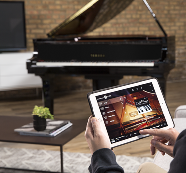
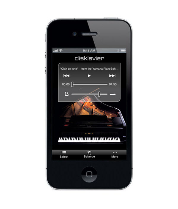
There is a sense of panic that sometimes occurs when musicians try to play along with pre-recorded backing tracks. They know that once they’ve started playback, they need to concentrate not only on striking the correct notes, but also on keeping up with the background arrangements. Even advanced musicians who ultimately master this art often view such an experience — which they liken to playing along with a metronome — as being confining and unfulfilling.
What is CueTIME?
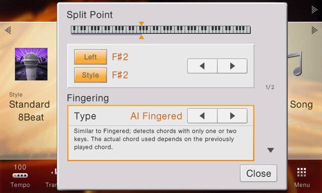
CueTIME software is designed to change this. Developed for exclusive use with select Yamaha Clavinova CVP keyboards (those equipped with guide lamps), it provides pre-recorded MIDI instrumental backgrounds that actually “wait” for you as you play along, giving you complete control over the tempo, regardless of how fast or how slowly you play on your keyboard. As a result, it introduces musicality to the experience by allowing for tempo expression such as ritardandos and accelerandos.
How does CueTIME work?
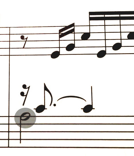
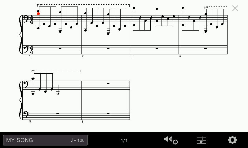
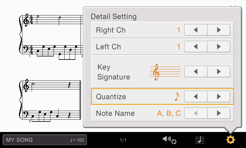
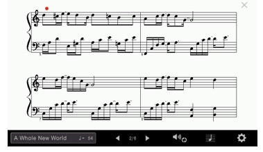
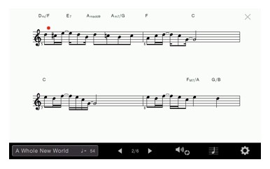
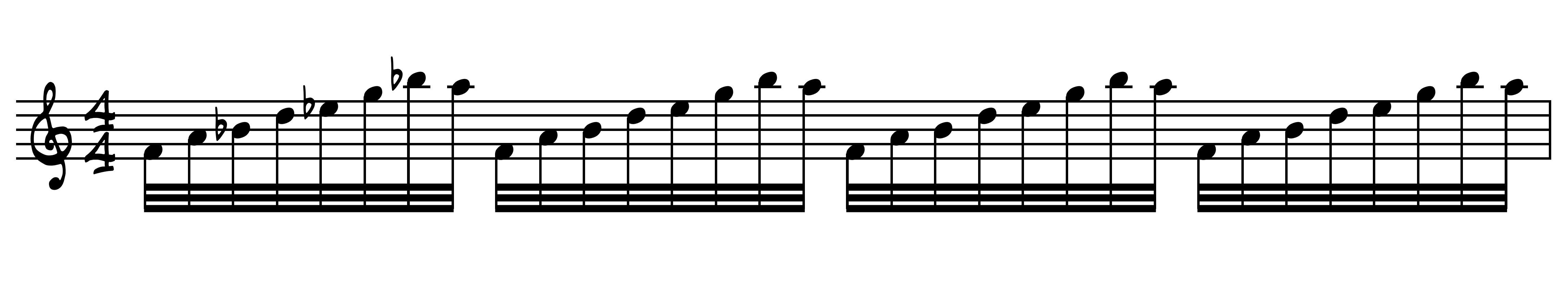
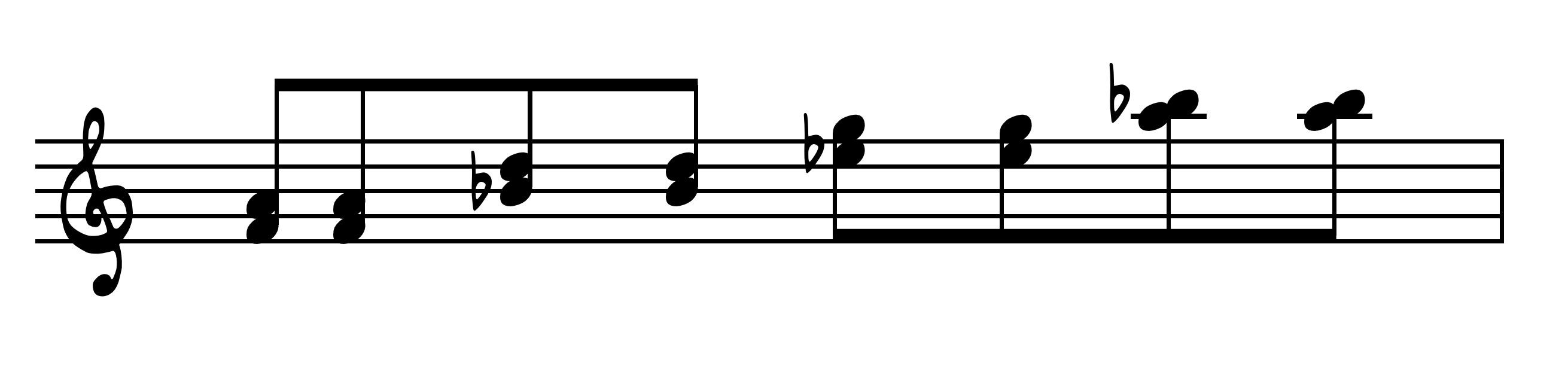
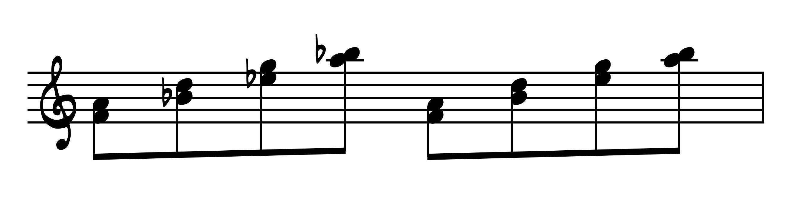
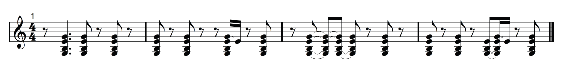
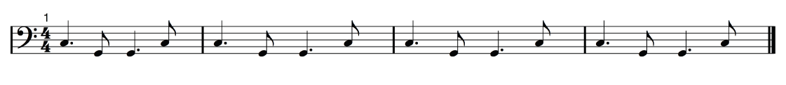
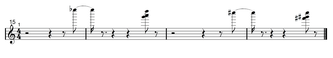
In the course of reading and playing a CueTIME selection, you’ll be striking strategically placed notes on the keyboard. These “cue notes” are used to advance the background sequence and are indicated on the printed music score with subtle highlighting consisting of a gray shading or a “halo” around the note head:
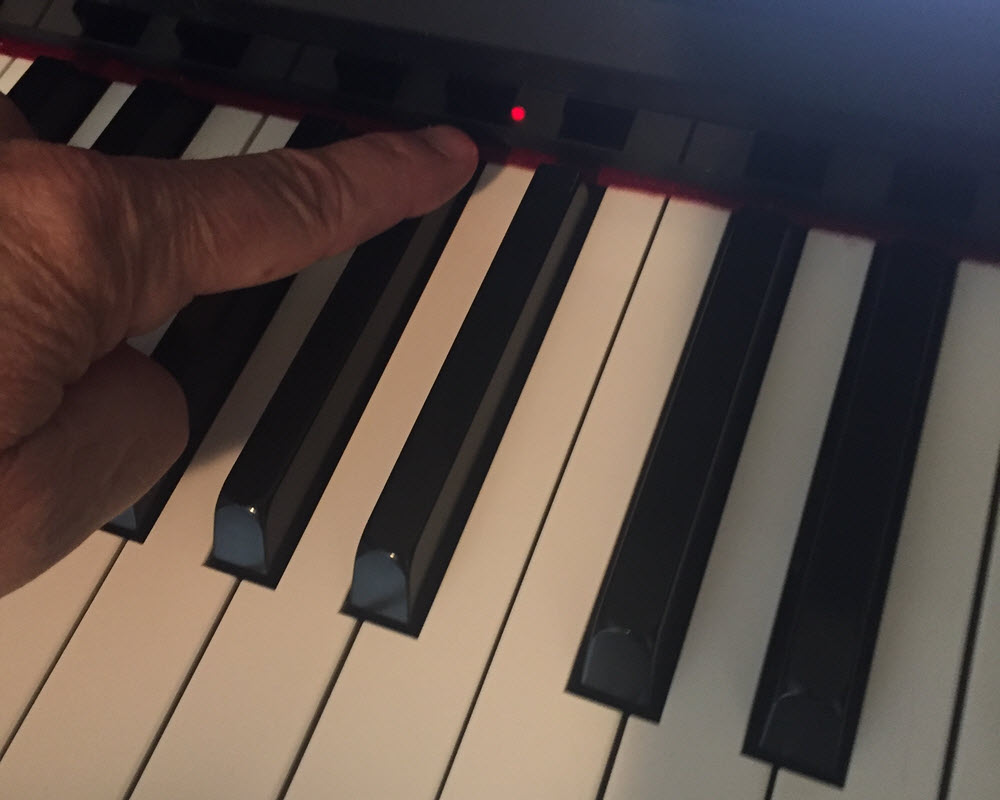
You can easily identify these “cue notes” on your Clavinova with the lights above each key:
How do I get CueTIME songs?
Every purchase of CueTIME is downloaded with a printable PDF version of the sheet music, along with the companion MIDI file. You can buy one song at a time, or in book collections of eight songs, and you can preview selections by listening to the brief MP3 audio samples next to each title on the website.
Now you’re ready to start playing along!
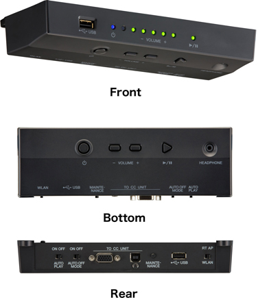
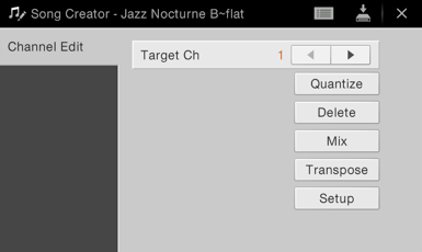
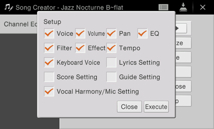
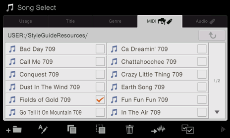
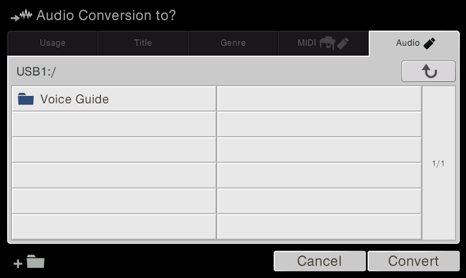
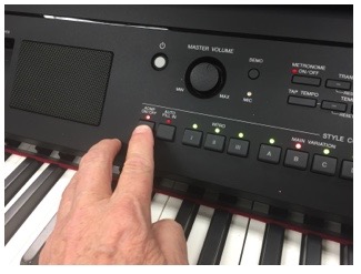
Begin by copying your downloaded MIDI files onto a USB thumb drive and then insert the drive into the USB port on your Clavinova. Now all you have to do is go to the “SONG” area of the instrument and load your purchases one song at a time. The “GUIDE” function — the feature that makes your Clavinova “wait” for you — is automatically activated when a CueTIME song is loaded.
When you press “Play” on the front panel of the Clavinova, you’ll see just one light appear above one of the keys — that’s the first cue. You won’t hear any background music until this note is played. If you then play the song exactly as written in the sheet music, you will activate all subsequent cues in the process.
Some hints when using CueTIME:
— Focus on reading the music.
— Slow down if you are unsure of the notes, because the Clavinova will adjust to your slower tempo as you learn the piece.
— If you miss a cue, simple look down at the keyboard and look for the light of the key you missed: that’s the note that the Clavinova is waiting for you to play.
— To determine where you are in the music, locate the “cue” note — one of the shaded (or “haloed”) notes in the music.
Jeff Coffin remembers listening to AM radio in the car as a child and being attracted to the emotional component of music. In fifth grade, he chose to play the saxophone in the school band program, or rather he believes that the saxophone chose him. “I think [the saxophone] is very close to the human voice, which is one of the reasons it appealed to me,” says Coffin, a three-time Grammy® Award winner. “I felt like I was able to emulate the voice.”
This initial attraction produced a passion for and a dedication to music that would lead Coffin to an incredible professional career: playing with both Béla Fleck and the Flecktones and the Dave Matthews Band (DMB), forming his own group — Jeff Coffin and the Mu’tet — and teaching music at the collegiate level and in clinics around the world.
Stick With It
In middle school, long before starting his professional career, Coffin wanted to “say goodbye” to his band program and music altogether. “All of my friends were deciding to play sports, which I also did, and I was like, ‘Man, I’m kind of done [with band],’” he says.
His director, Arthur Lagassee, asked him to stay at least through the annual Christmas concert. Out of respect for Lagassee, Coffin stayed and never looked back. “I can’t imagine what my life would have been like had I quit band,” he says.
To keep young students interested in music, Coffin encourages directors to make rehearsals creative and fun. “[Students] want to have something that interests them. Get them improvising immediately. Get them doing call and response and get them listening to different kinds of music. Open them up and talk to them.”
In seventh grade, Coffin began playing with Lagassee’s trio, a defining moment in his musical career. “I got the bug,” he says. The bug was powerful enough to keep him involved in music throughout his high school years and land him in the music education program at the University of North Texas.
On Tour
After college, Coffin moved to Nashville, Tennessee, and began running jam sessions while teaching private lessons on the side. As luck would have it, a musician who knew Béla Fleck attended one of these sessions. Impressed with Coffin’s talent, he introduced him to Fleck, who then asked Coffin to go on tour with the Flecktones. Coffin spent the next 14 years as a Flecktone, during which time the group would often open for the Dave Matthews Band. In 2008, when DMB saxophonist LeRoi Moore was injured in an accident and later died, Coffin took his place with the band. “The Flecktones had been taking some time off,” Coffin says, “so, with [their] blessing, I took the Dave Matthews gig.”
During his time outside of these groups, Coffin also started his own band: Jeff Coffin and the Mu’tet — an ensemble that has been comprised of the same people for about 16 years and has recorded 10 CDs. “Being a leader is the most difficult thing I’ve ever done,” Coffin says about the Mu’tet. “I have to deal with all the merchandise, I have to deal with the assistants, I’ve got to deal with management, club owners, booking agents. There’s a plethora of things that I have to do that [the other members do not]. And I have to get up on stage and be the lead guy.”
Despite the difficulty of leading a band, Coffin consistently thinks outside the box and is a true innovator in his professional career. For years, he has used pedals on his horns, just as a guitarist would, to alter the sound of the saxophone and give himself more of a sonic pallet to choose from — because why should guitarists have all the fun?!
The sounds he was able to create with the pedals inspired him to learn a unique skill — playing two saxophones at once. “It’s fun, it’s a cool sound, it’s interesting, it’s experimental, it’s visually appealing to people, but it’s just a tiny part of what I do,” Coffin says.
On The Flip Side
To further his musical expression, Coffin composes and started his own record label, Ear Up Records. The company name derives from Coffin’s belief that listening is one of the most crucial components of musicianship. “The philosophy of the label is that it’s all handpicked by musicians, and it has to do with the artistic integrity, not the commercial potentiality of it,” he says.
In art as in life, Coffin takes advantage of many opportunities for personal growth. In his spare time, for example, he explores his creativity as an avid photographer. This pursuit of personal growth gave Coffin new insights as an educator.
Tailor Your Teaching
In Coffin’s latest gig as a professor of jazz studies, he teaches saxophone studio lessons and works with the top jazz ensemble at his university. The most important part of his teaching process is talking to his students about what they want to learn in order to tailor his lessons.
“Get to know them as people, not just as students,” Coffin says. “They are fertile minds and are looking for direction and guidance. Don’t make it about you. It’s all about them. There are many ways to reach students, and it’s our job as educators to expand the way we educate to fit the way the student learns.”
When he’s not busy rocking out on stage or in the classroom, Coffin leaves his stomping grounds in Tennessee and travels the world, giving clinics, master classes and lessons. “I involve the students from the very beginning of the clinic, and we talk about a wide variety of things — from why we do long tones to the aesthetic nature of music and how it relates to us as sentient beings,” explains Coffin. During these sessions, he encourages a lot of questions. “I try to get the students to be curious and to draw ideas and concepts out of what I present to them,” he says. “I basically allow them to be creative in their thought process and to provide a safe space for them to ask questions — no matter how ‘far out’ those questions might be.”
These clinics have given Coffin the opportunity to travel off the beaten path to unique places, including Havana, Cuba, and Tuva, a republic of Russia located in southern Siberia. “I’m really fortunate that music has taken me to a lot of very unique and unusual places around the globe,” he remarks. “I’m very thankful every day for that.”
For students wishing to pursue a career in professional performance, Coffin says that fundamentals are key. His three volume book, The Saxophone Book, (www.thesaxophonebook.com) discusses what Coffin calls “The Big Five” of fundamentals: listening, tone and dynamics, articulation, rhythm and time, and harmony.
Through his presentations and in his university classes, Coffin feels he learns as much as he teaches. “We are there to learn together, and I feel that I am a student most times, and they are the teachers,” he reports. Yet even as a prominent performer and educator, Coffin will always consider himself to be, above all, a student. “Stay open and realize that you have a lot to learn,” he says. “The moment you stop being a student is the moment you need to stop teaching.”
Photo Courtesy of Alysse Gafkjen for Yamaha Corporation of America. Photo (c) 2017 Carol Mackay Photography. All rights reserved.
When Daniel Berard walked into his job interview at Fossil Ridge High School in Fort Collins, Colorado in 2004, he had a clear vision of how to start the band program from scratch. He pictured the program one, two, five and 10 years down the road and hoped the administration would buy into his plans.
“I laid out what I thought we might be able to do at Fossil Ridge, and that resonated with the people who opened the building,” recalls Berard, who had previously been a high school band director for 10 years before working toward his master’s degree in music education and instrumental conducting at Colorado State University.
Berard became a critical member on a core team of about a dozen individuals who opened the high school. Since the birth of the band program, he has striven for music excellence at Fossil Ridge as the performing arts department chair for the last 10 years and currently as the director of bands.
Then-principal Dr. Dierdre Cook wanted the band program to set the school apart from others, citing it as “one of the foundational cornerstones” for a successful high school. “I knew a marching band would be important, and I knew it had to be the right band director, and Dan Berard is the right band director,” she says.
The band program has about 180 students this year, but 13 years ago, it had only 20 students. Over the years, the school’s bands have won several awards. The Wind Symphony and Symphonic Band received superior ratings at state and regional concert band festivals, and the marching band has been a state championship finalist every year since 2005, winning the 2012 and 2013 Colorado Class 5A marching band championships.
Baby Steps
As the Fossil Ridge band program took life before his eyes, Berard says the first few years involved pumping blood into the group to get it up and running. “As we were getting going, we were just taking little baby steps along the way to make sure that every time we took a step forward, it was something that [the students and administration] could feel good about,” Berard explains. “Then we just built from there, slowly and methodically, kind of putting things in place.”
The three other high schools in the area had bands, but they did not really participate in marching activities, Berard says, so nurturing the band program in a community without a strong marching culture was the hardest part in the beginning.
To grow the marching arts at Fossil Ridge, Berard analyzed successful bands from across the country. “It’s matching what we wanted to do with what was happening from around the country and tailoring it to what our situation was going to be,” he says.
His firsthand observation of other groups helped him determine the structure of his rehearsals, how to keep students motivated and how to operate the chamber ensembles. Berard also pulled from his own personal experiences learning the value of patience and the business of band.
Gauging Success
Logistically at Fossil Ridge, the students are split into three sit-down bands — concert band, Symphonic Band and Wind Symphony — starting with the first day of school. These three bands combine to make up the marching band in the fall. After marching season, students continue playing in the concert bands for the rest of the school year and perform in several small ensembles during the second quarter. Color guard members continue their training through a spring dance program.
While the program earned several awards over the years, Berard says he does not solely use those accomplishments to measure the bands’ successes — he also gauges everyday accomplishments during practices and dress rehearsals. “There’s a lot of what the community sees as being really successful,” he explains. “[If] you win a couple of state championships or something for marching band, everybody thinks things are great, which it is, but from the inside, I see it a little differently. The growth of the program is [measured] by having kids rally around achieving this really, really high level, and that sets the standard on a daily level. It was great to do some of these high-profile performances, but what we do every day establishes our opportunity to do some of those bigger things.”
The little successes, says Berard, snowball into large successes. Two of those pivotal moments came in 2012 and 2016 when the Wind Symphony performed at the Music for All National Festival. Berard submitted an audition video on a whim in 2012, and the performance became the first “award” from a concert band standpoint. “That started this special climb because the kids really rallied around what that meant for them and the school,” he remembers. “They knew they would be performing with some of the very best groups in the country, and that just kind of elevated everybody. That group of students set a new standard for what they wanted out of the band program, and that really challenged me. I had to get a lot better because they wanted to get a lot better.” And when the symphony went back four years later, he says the performance set even higher standards for the program.
The Heartbeat of the School
Berard says several people have spurred the band’s success over the years, with the students and administration being the driving force. Cook, on the other hand, credits Berard — who she calls the “heartbeat of the school.”
“Those kids learn skills they wouldn’t learn from anywhere else, and he rallies kids to that level of excellence,” says Cook. “Dan moves it to the next level because he believes in the quality of the program and he believes in the talent of those kids, and he’s able to bring that out and have them be successful.”
The skills students learn in band go beyond the music and technical side of playing; they learn responsibilities and lessons that translate both on and off the field, according to Cook. Seeing band students working on homework while riding the bus is a common scene at Fossil Ridge High School because they understand responsibility. The music students have higher GPAs and college acceptance rates along with less disciplinary problems.
French horn and mellophone player Morgan Herrick understands firsthand how the program helps students grow musically and academically. “The competitive nature of band and how successful our band is kind of pushes you, especially as young high schoolers, because you realize how you have a part in the whole,” says Herrick, a May 2017 graduate. “It’s your responsibility as an individual to be a part of something bigger and to help the group. I think that’s a really good skill for people going into high school — to start learning right from the beginning.”
While band programs may be expensive, Cook says that the rewards outweigh the costs because they allow students to explore future opportunities, like college scholarships and university and military bands.
Creating a Legacy
Looking back on 13 years of the band program and how it all started, Berard calls the band’s success “magical.” The band met his 10-year goals in its seventh and eighth years, but maintaining this success could be even harder, he warns.
“Going from a 95 percent to a 96 percent is way harder than going from a 50 percent to a 90 percent,” explains Berard. “It’s that one percent that is almost impossible to get to. It’s that whole ‘good-to-great’ threshold.”
Embracing music technology and discovering different ways to keep students’ attention are just a couple of Berard’s current goals. With the foundation of the band now set, these “little” goals will eventually lead to the long-term health of the program and, Berard adds, hopefully create a legacy that will continue to live on.
This article originally appeared in the 2017 V4 issue of Yamaha SupportED. To see more back issues, find out about Yamaha resources for music educators, or sign up to be notified when the next issue is available, click here.
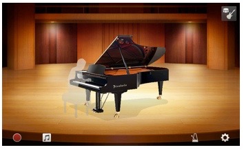
What do you get when the world’s largest manufacturer of musical instruments (that’s Yamaha!) and the world’s largest distributor of sheet music team up to create something fun and unique?
The answer is You Are The Artist, a collaboration between Yamaha and Hal Leonard that will get you playing along to your favorite songs by your favorite artists, on your favorite Yamaha digital keyboards.
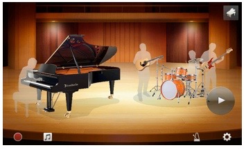
What makes You Are The Artist unique is that in addition to print music by popular and iconic artists such as Adele, The Beatles, Coldplay, Elton John and more, the equivalent MIDI files can be purchased right along with printable sheet music — two files designed to be used with one another. While it’s fulfilling to learn how to play your favorite songs, playing along with a backing band takes it to a whole new level.
Every MIDI file in the You Are The Artist collection has been created to take advantage of some of the very best sounds in your keyboard — the Yamaha XG voices. These voices are incredibly realistic, and are showcased in the arrangements. And because these song files are in MIDI file format — not audio file format — you have total control over the music. You can change the speed, mute and solo various tracks – even use the learning features on your instrument to help you master the songs.
To get started, simply visit the You Are The Artist page in the Yamaha Downloadableswebsite. After selecting a song title, you’ll notice that you have three options: You can purchase just the backing track, just the sheet music or both bundled together.
The sheet music you purchase can be viewed and printed as a downloadable PDF file or through the interactive sheet music viewer.
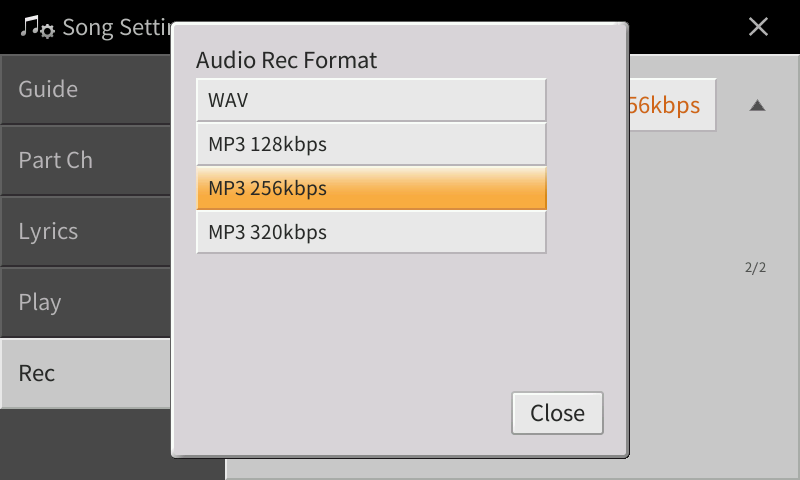
To get the MIDI file with the backing tracks out of your computer and into your keyboard, you’ll need a USB thumb drive. (As a rule of “thumb,” it’s best to use a drive no larger than eight gigs since smaller drives tend to be more compatible with keyboards.) Insert it into your computer, then drag the MIDI file from your download location (which may be your desktop, or a “Downloads” folder) to the thumb drive. Next, eject the drive from your computer and place it in the “to device” port on your keyboard. (The location of this port will vary from instrument to instrument.) The process of loading a MIDI file will vary as well, but generally, SONG MODE is a good place to start. (Refer to your keyboard’s documentation for detailed instructions.)
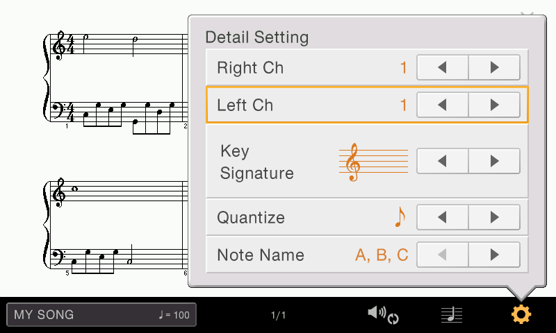
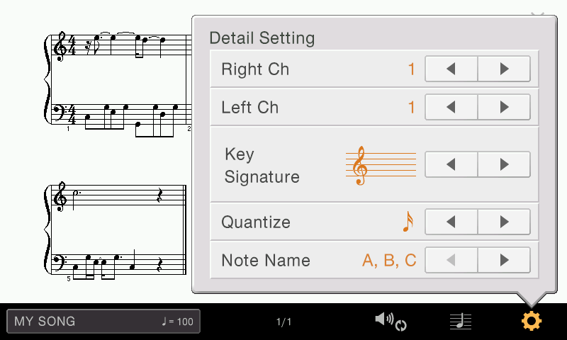
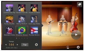
Once your selected MIDI file is loaded in your keyboard, you have a number of options in addition to basic song playback. You can slow the tempo down, which makes it easier to learn more complex musical passages. You can mute certain backing tracks if you’d rather play the instrumentation yourself. You can even select which part you’d like to practice — the left hand part or the right hand part.
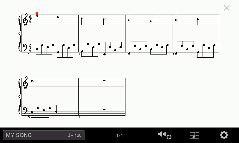
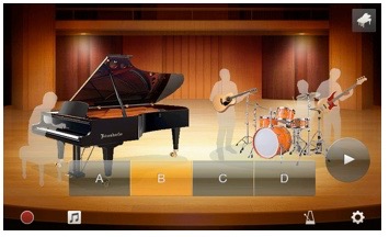
But by far one of the coolest features in many Yamaha keyboards — something that works incredibly well with YATA song files — is the ability to put a song in what we call “guide” (or “waiting”) mode. In conjunction with the Score Display, this will pause the music until you play the correct note or notes, so you’re never rushing to catch up. If you have a CVP or CSP Clavinova, you can even take advantage of its Follow Lights (or Stream Lights) feature, which illuminates a light above every key, showing you which keys to play next.
Another big advantage is that MIDI files take up very little space, which means that you can store literally hundreds of MIDI songs on a single USB thumb drive. So go crazy, load up on You Are The Artist songs and get started playing the songs that you love!
A music professor once said to me, “My role is not to teach you how to play, but how to practice.” The statement probably had something to do with practicing slowly, a habit that can take a long time to master.
As students, our inclination is to follow direction, but it’s important to understand the benefits of practicing slowly, regardless of the instrument you are learning. You may have the sense that doing this worked well in the early stages, but that it may not be as necessary to practice slowly later on. In fact, once you know the notes, it can seem mind-numbing to slow a piece down to half or quarter of the performance tempo. It hardly seems an effective use of time to spend half an hour on less than ten measures of music, especially when the performance date is coming up soon. You could run a whole piece two or three times in those thirty minutes. Why practice slowly, unless it is to initially learn notes and rhythms?
There are three reasons why. Let’s look at each of them in turn.
Listening
Not only does slow practice provide the benefit of playing accurately, it allows you to better hear and evaluate your performance. You’ll be able to identify subtle nuances and inflections that may be difficult to discern at full tempo. You can control the character and timbre to produce a sound that matches your intended interpretation. Slow practice will get you noticeable results on all instruments, from cleaner articulation when playing trumpet to flawless pitch while practicing timpani.
Muscle Memory
In order to form muscle memory, the movement you’re trying to retain must be repeated many times. Slow practice allows the muscles in your hands and other parts of the body to adjust to repetition. Once this is achieved, it’s important to stay engaged and avoid going into “auto-pilot” mode when practicing at full tempo. Finding a balance is key to developing muscle memory.
Clarity
Slow practicing encourages clean technique with no hiccups or slop between the notes. Each musical moment is defined and communicated clearly. With this method, you’ll worry less about the quantity of notes you learn, and more about the quality of sound you can produce.
Start today by picking an étude or scale you’re working on and play it slowly. Take a deep breath and resist the urge to speed through your practice session. Your next performance will thank you for it!
Failing to recognize when your child is ready for a new violin can hinder their progress in learning a string instrument. Many factors can contribute to the need for a new instrument. Here are some signs that will let you know when your child is ready:
1. Improperly-sized instrument — the “Goldilocks factor.”
The most common reason for a younger player to require a new instrument is size. A violin that fits a student perfectly will quickly become too small when their growth spurts hit.
Want to check? Have your child extend their left arm out to the scroll of the instrument and wrap their fingers over the scroll. If the fingertips reach into the peg box (the component that houses the tuning pegs) and there is just a slight bend in the elbow, the instrument sizing is correct. If the elbow bends into a sharper angle, it’s time for a larger instrument. A trip to a local dealer will help you find an instrument that fits just right.
2. Poor instrument condition — Grampa’s fiddle from the attic.
It’s not uncommon for a family to have an heirloom instrument that’s been passed down through generations. However, most are not kept in good playing condition. An instrument that is in poor playing condition can affect a student’s playing skills. Open seams and cracks cause loss of tone and buzzing. Bumps in fingerboards and pegs that slip or stick can cause intonation problems.
Before putting any antique instrument in your child’s hands, have a knowledgeable luthier evaluate its condition and assess what repair work may be needed. Many times the cost of putting an instrument back into playing condition exceeds its value – or even the cost of a new one. If a student struggles with playing problems but still shows interest and initiative to learn, investing in a new instrument that has been properly constructed and shop-adjusted by a luthier will help them take a big step forward. It’s often better to appreciate the heirloom on a bookshelf or mantle.
3. Your child is growing more enthusiastic — practicing to perfection.
When your child is making an effort to increase their playing skills, take notice. Is this something that they might want to keep doing for the rest of their school years – or perhaps even the rest of their life? Are they starting to compete in solo festivals? If so, then start thinking about a good intermediate or advanced instrument that can last through their high school years and beyond.
4. Your child is in a strong music program — not all are created equal.
The strength of a music program may create the need for a better instrument for your child. An enthusiastic and capable mix of educators, administrators and community support is what builds high-functioning performing groups. These groups often travel to festivals and competitions where they are rated against other strong programs. If this is the case, a better instrument not only helps the overall sound of the performing group, but makes it easier for your child to keep up with the demanding challenges of increasingly advanced musical works.
5. Your child is graduating to a new school level — Pomp and Circumstance.
Advancing through grades brings increased challenges in a student’s curriculum. Moving from elementary school to middle school – and from middle school to high school – are also big steps in your child’s musical life. It’s important that students have a well-made and good-sounding instrument that will be up to the job as they advance through grade levels. A new step-up instrument serves as a reward for their efforts and will provide them with enjoyable experiences through their high school career and beyond.
So if you’ve questioned whether or not your child is ready for a new instrument, these are some scenarios that may provide you with an answer. Any of these is a very valid reason to talk to your child’s teachers or local music retailer to see what steps you should take next to support their development. It’s the best thing that a parent can do to assure that they helping to provide their child with a well-rounded musical life.
Click here to learn more about Yamaha violins and other string instruments.
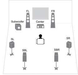
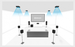
DTS Virtual:X™ is the latest innovation from our friends at DTS, the company that brought us DTS:X – the object-based audio technology featured in movie theaters and many Yamaha sound bars and AV receivers.
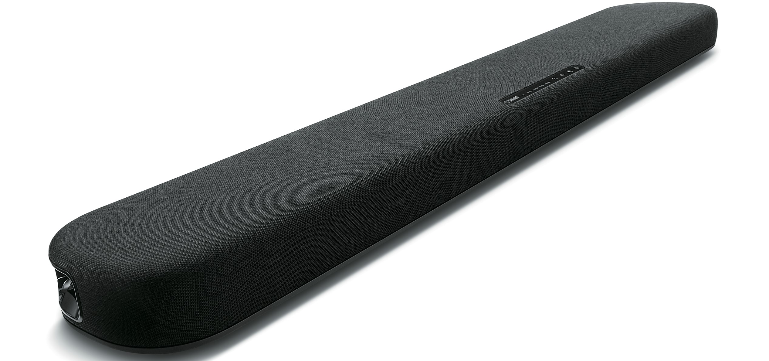
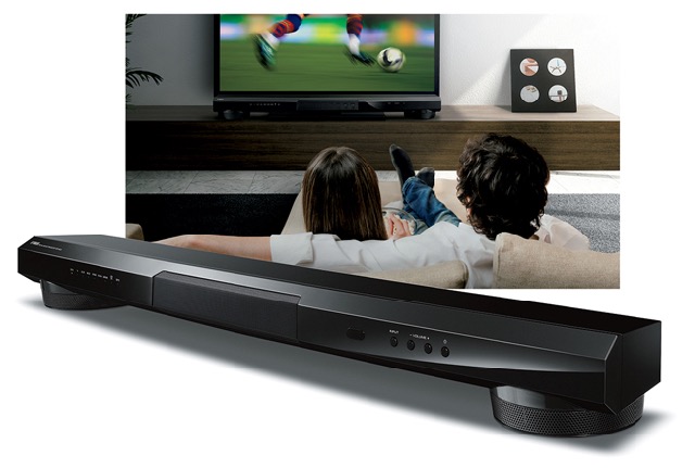
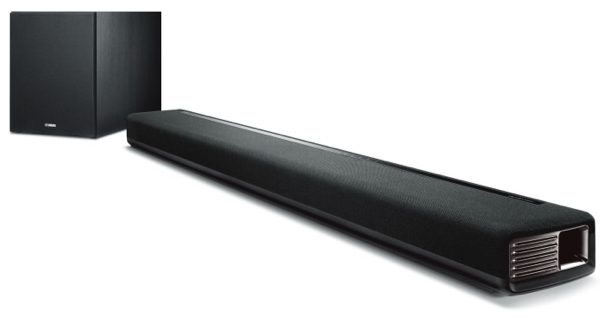
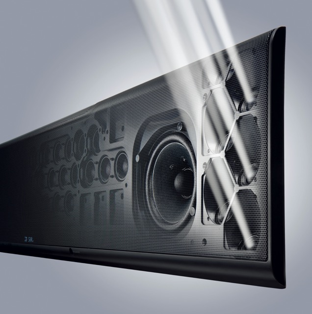
DTS Virtual:X uses proprietary audio processing techniques inside the sound bar to create spacious 3D sound – including the sensation of height – from any content, and without the need for in‑ceiling or upward-firing speakers. In other words, you’ll enjoy a wider, higher, more immersive audio experience from your favorite TV show or football game when you listen to it through a DTS Virtual:X-enabled sound bar such as the Yamaha SR-B20A.
Unbelievable? Well, you better believe it, because your mind does. DTS Virtual:X uses intricate audio cues to tell your brain where sounds are coming from, even when they’re not. The result is ambient sound that seems to surround you while dialogue stays centered. And because these results are achieved digitally – and not from wall or ceiling reflections – it doesn’t matter what the size or shape of your room is.
Yamaha SR-B20A sound bar.
DTS Virtual:X can take full advantage of a full-blown 7.1.4-channel system to produce stunning three-dimensional sound with robust height channels. And while such a system may be your ultimate goal, DTS Virtual:X can also do wonders with even modest speaker configurations. In fact, it’s especially well-suited for sound bars because of their small form factor.
Thanks to DTS Virtual:X, you don’t need a full-blown home theater setup to enjoy 3D surround sound.
As you may have noticed, the spaces between the frets on the neck of a guitar grow narrower the closer to the body they are.
Why is this?
Well, each time you move one fret closer to the body, the pitch increases by a semitone. A very simplified way to calculate how much a string should be shortened in order to raise its pitch a semitone is to take the original length of the string and multiply it by 0.944. In other words, the distance between each fret is narrower and narrower as you go higher in pitch.
Of course, this is only a theoretical number. In reality, a variety of factors (such as tension offset) must be considered and a much more complicated formula is used to calculate the exact positions of frets in well-designed guitars.
Speaking of frets, did you know that “cutaway” style guitars (like the Yamaha model in the picture above) make it easier to access upper frets?
As the name suggests, a cutaway in a guitar refers to an indentation that looks like a part of the guitar was “cut away” from the body. With this type of guitar, the body is shaped so that the fretting hand can more easily access the frets closer to the body (i.e., the higher notes). This allows a guitarist to easily reach the very highest frets, although in cutaway acoustic guitars, the sound can suffer to some degree due to the indentations in the body. However, this does not pose any significant problem for electric or electric-acoustic guitars.
Have you ever found yourself leaning toward the TV straining to hear what’s happening during your game? Sometimes dialogue in movies and commentary in newscasts or sporting events can be difficult to understand.
Why is that? It’s because sound effects and background noise can compete with the sound of human voices.
Clear Voice to the rescue! This feature, found in many Yamaha sound bars, brings dialogue and narration to the forefront – making voices easier to hear and understand. Or in nerd-speak, “The vocal frequency range and its harmonics are emphasized for greater intelligibility while remaining frequency components are attenuated.”
So turn on Clear Voice, and when they say:
“This team’s chances of winning are slim.”
You won’t hear:
“Team advances with convincing win.”
Click here for more information about Yamaha sound bars.
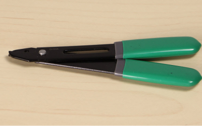
It is inevitable in the life of every string player that they will encounter a sudden distracting buzzing sound coming from their instrument. Fixes can range from the simplest of tweaks to a major repair that requires a skilled luthier.
Luckily, most buzzing is caused by a loose fitting on an instrument — something that’s simple to diagnose and easily fixed.
Follow these five steps to get your instrument back into playing condition:
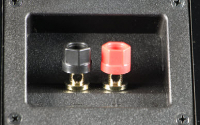
1. String fine tuners. These can loosen not only at the screw that’s used to tighten the string, but also at the nut that locks the tuner to the tailpiece. The more such hardware you have on your instrument, the more likely they are the cause of the buzz. Make sure each tuning screw is tight and then check the lock nuts to make sure that none of them have vibrated loose.
2. Chinrest and hardware. Check the turnbuckle that tightens the chinrest to the instrument. If this loosens, the result is often not only a buzz, but a chinrest that comes off altogether! A little careful tightening assures a quiet chinrest that stays attached.
3. Tailpiece and tail adjuster. Ideally the tailpiece should never contact the saddle or the top of the instrument. A tailpiece that is tightened too far down the tail adjuster can not only cause a buzz or a rattle — it can inhibit the tone of the instrument. Loosening the tail adjuster by one or two millimeters can quickly remedy this problem.
4. Loose string windings. A common culprit is string windings becoming loose. Many times they are hard to see, but they can cause buzzing from the bridge area all the way to the fingerboard nut. Running your fingertip up and down the entire length of each string can reveal a rough spot that can be the beginning of an unraveling winding. If you detect this, replace the string immediately.
5. Ornamental pegs. While decorative collars are attractive, over time they can come loose and become the source of a buzz. Push on the collars to see if any come free from the shaft of the peg. If that happens, they can easily be refastened with a drop of super glue.
While these are the most likely causes of a buzz, there are several other, considerably more complicated possibilities. If you have checked the fittings carefully and found no obvious cause for the sound, the culprit could be an open seam, a lining that has come loose, or — in very rare cases — a bass bar that has loosened. All of these require a visit to a luthier to diagnose and repair the instrument back to a healthy state.
It’s important for every string player to remember that their instrument was once a living, breathing organism. It consumed water and exchanged gasses with the environment around it and changed constantly. Even in its current state it constantly reacts to its surroundings, and as those surroundings change, your instrument changes as well. Sometimes those changes can cause a sudden buzz that can not only be annoying to the player, but detrimental to the instrument if allowed to continue.
Keeping these steps in mind when first detecting an unwanted vibration will give you the skills to do an accurate diagnosis of the cause. More importantly, knowing what parts are likely to come loose can lead you to a fast remedy — invaluable should you ever find your instrument buzzing just before you take the stage! There is nothing more rewarding to a performer than to hear their instrument delivering the very best sound it is capable of producing.
Click here to learn more about Yamaha violins and other string instruments.
If you’ve ever listened to a radio personality, you have most definitely heard the sound of a compressor. No matter whether they are talking in a whisper or a very loud voice, the sound level from your radio stays pretty much the same. It’s as if someone is “riding the fader” — turning the microphone input up and down according to how loud the person is talking. A compressor can do this, and more.
In its simplest terms, a compressor reduces dynamic range – the difference between the loudest and the quietest sounds in a mix. Loud sounds are lowered so that they fit below the maximum levels desired, which in turn causes quiet sounds to appear louder (i.e., more prominent) in the mix.
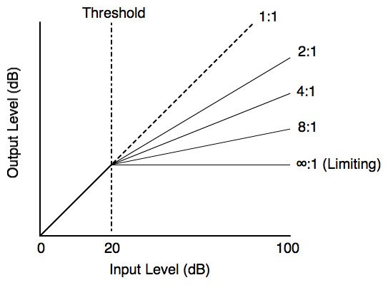
Compression ratio graph
Compression on input channels is a common tool used both in live and studio settings to accomplish several things:
Help tame or reduce the dynamic range of an instrument or vocal. A good example might be a vocalist who whispers the verses but really projects during the chorus. The compressor holds back the parts being belted out, which effectively raises the apparent level of the whispers. The end result is a sound that is more consistent.
Bring an instrument more “forward” in the mix. This might be a kick drum or bass guitar that is not being heard over the other instruments. A compressor can do a great job here in increasing the perceived loudness of the instrument(s) that need the help.
Maintain the levels of a person talking at a podium so that every word can be easily heard and understood.
Used on the output side, compression can:
Remove some of the highest overall output levels to make the audio output “fit” into the limitations of the system. In live sound, a system’s lowest level is a function of crowd noise and other environmental sounds, while its upper range is determined by either the maximum output of the amplifiers being used — or when the neighbors start to complain!
Protect the system from damage due to overloads. Some professionals call compressors “limiters” (or “comp/limiters”) which is really redundant, since a limiter is actually just a compressor set very aggressively to “limit,” or govern the output so as not to exceed a set maximum level. See infinity (“∞ : 1”) in the graph above.
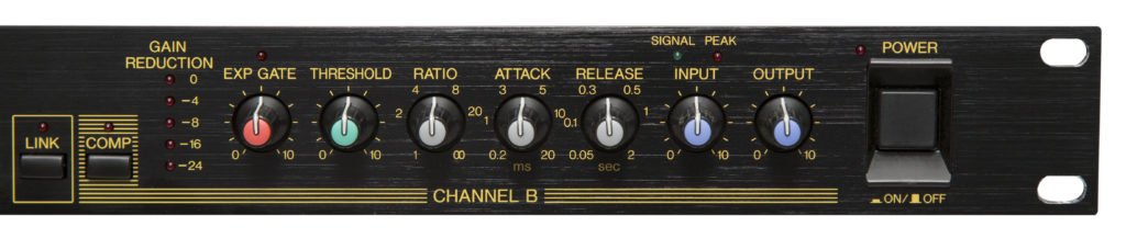
Typical analog compressor controls
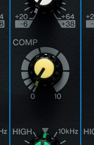
Yamaha MG series 1-knob compressor control
After seeing how frustrating and confusing it can be for live sound people to adjust a compressor with all its different parameters — often right in the middle of the performance! — Yamaha pioneered the 1-knob™ compressor you’ll find on our MG and MGP series analog mixers. This takes all the guesswork out of setting and operation.
For instance, when a compressor is reducing levels it becomes necessary to add some gain or level to compensate for lost level. Our engineers found a way to make adjustments to multiple parameters — not just “makeup” gain, but advanced controls like “threshold,” “ratio,” “attack” and “release” — with a single knob. The ultimate goal was to allow you to get back to the performance … and not need a degree in audio engineering to use a compressor effectively.
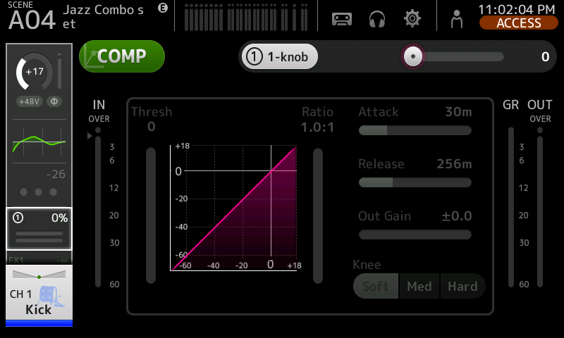
Similar 1-knob compressors are also offered on some Yamaha digital consoles (like the TF series) so pro users can get results quickly.
Yamaha TF series 1-knob COMP™ screen
Compression Advice
When setting a compressor for the first time, use something other than your voice to check or adjust it. Because of the way we hear our own voice through vibrations in the bone structures of our head, subtle effect changes (including compression) can be very difficult to perceive. Over time, and with practice, you’ll develop this ability — but using another voice or an instrument will give better results.
While compression can be very helpful, there are also some potential drawbacks. In a live setting, as you increase the amount and number of compressors, you reduce the maximum potential gain or output of your PA system. In other words, feedback will occur sooner. Follow this rule: Use compression when necessary but avoid overuse.
When using compression with singers in particular, be aware that since you are “squeezing” their dynamic range this will affect what they hear too. So take care to add compression lightly, and only as needed, so as not to affect their performance.
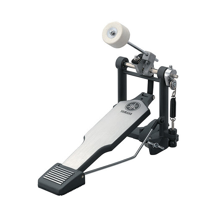
In the early days of the drum pedal, there was one type in which the beater was attached to the top of the bass drum rim (the frame that attaches the skin of the drum, called the head, to the body, called the shell), and another type in which the beater was attached to the bottom of the rim, as they are in today’s drum kits. The pedals were made of wood and were not spring-loaded, so the beater had to be returned to the ready position using the foot.
The spring return mechanism of today’s pedals was introduced in 1910. In 1934, ball bearings were added to create a smoother pedal action, and in 1950, the spring was built into the frame, improving the look and allowing for finer adjustment of the foot pedal – improvements that many drummers supported.
The next breakthrough was the chain-driven pedal. Near the end of the 1970s, a craftsman at a drum store in New York removed the pedal’s drive mechanism and replaced it with gears and a chain taken from a bicycle. Prior to that, there were pedals with metal parts connecting the drive mechanism, and those that used a belt made of nylon or other material. The former were said to have a “quick response,” while the latter were said to have a little “play” in them. The chain drive combined the best aspects of these two approaches to create a robust pedal that quickly gained wide acceptance.
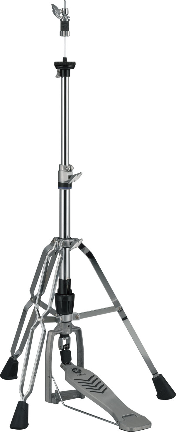
The First Hi-Hat Looked Like a Snowshoe
The hi-hat taps out 8-beat and 16-beat rhythms clearly, and sets the rhythm of music along with the snare drum and bass drum. However, the emergence of the hi-hat is surprisingly recent, and the hi-hat as we know it today was invented around 1930.
The original hi-hat consisted of two small cymbals attached to two boards, one on top of the other, joined with a hinge. The upper board was attached to the foot with a strap like a sandal, which made it look like a snowshoe, and thus it was actually called “the snowshoe.” When famous jazz drummer Baby Dodds was playing on a Mississippi riverboat, he tapped the floor with his left foot in tempo with the music, and seeing this, an enthusiastic fan fashioned a device that enabled him to clash two cymbals together using a foot pedal, which is said to be the beginning of the development of the hi-hat.
You’ve just purchased that awesome AV receiver, speaker or sound bar you’ve had your eye on. If it’s a Yamaha product, it comes with a great warranty that includes parts and labor, and even if it’s a product made by a different manufacturer, it probably comes with some kind of coverage. Either way, you think you’re golden.
Well, like any legal document, there’s fine print. And since many of us don’t take the time to read every one of those tiny, barely-there words, here are some suggestions for what NOT to do if you want to keep your warranty in force:
1. Use your AV receiver as a step stool.
If you send your receiver back with a giant dent in it because Junior used it to help reach the cookie jar on top of the fridge, don’t expect a replacement. This is high-tech gear we’re talking about, and while it may well be solidly built of the finest quality heavy-duty materials, there are limits. You simply cannot expect help from the manufacturer if you abuse the equipment.
The phrase “under normal use and service” in the Yamaha warranty is typical language:
“YAMAHA will, at its option, repair or replace the product covered by this warranty if it becomes defective, malfunctions or otherwise fails to conform to this warranty under normal use and service during the term of this warranty, without charge for labor or materials.”
2. Let your friend Joe “crack ’er open” to figure out why your amp isn’t amplifying.
A surprising number of self-proclaimed “audio experts” attempt to fix something perceived as “wrong” with a new piece of AV gear, realize they can’t, and then send it in to the manufacturer to get the job done right. But if Joe has already given it a shot and failed, your warranty will fail too. The experts at your manufacturer will still be happy to fix whatever the issue is, but you’ll have to pay for it.
Here’s what Yamaha has to say about the matter, which is the approach pretty much any AV manufacturer will take:
“This warranty does not cover repair or attempted repair by anyone other than YAMAHA or an authorized YAMAHA Service Center.”
3. Use your wireless speakers in the shower.
Many speakers, sound bars and receivers do fine indoors in humid climates – certainly the ones made by Yamaha do. But that kind of equipment doesn’t do nearly as well when constantly exposed to high levels of humidity, such as in a small bathroom. Deterioration due to precipitation or other external causes such as extremes in temperature or humidity will void your warranty faster than you can say, “Will somebody bring me a towel?”
The Yamaha warranty addresses the issue this way:
“This warranty does not cover damage, deterioration or malfunction resulting from perspiration, corrosive atmosphere or other external causes such as extremes in temperature or humidity.”
4. Jury-rig your sound bar as a karaoke device.
A sound bar is an absolutely fantastic solution for improving TV audio. But if you alter it in a way it wasn’t intended – say, you manage to take off the back panel and hot-wire a microphone for a night of a capella oldies – you’ll lose out on any warranty coverage if something goes wrong.
Or, as the Yamaha warranty states:
“This warranty does not cover damage, deterioration or malfunction resulting from accident, negligence, misuse, abuse, improper installation or operation or failure to follow instructions according to the Owner’s Manual for this product.”
5. Dig someone else’s non-working receiver out of a dumpster and send it in for repairs.
Yes, this actually happened. The erstwhile owner of said receiver was disappointed to discover that, no, he couldn’t get it repaired for free under warranty.
Typical of most AV warranties, Yamaha puts it this way:
“Any evidence of alteration, erasing or forgery of proof-of-purchase documents will cause this warranty to be void. This warranty covers only the Original Owner and is not transferable.”
Warranties Are Your Friend
In all the excitement of installing your new AV gear, you may want to pause for a bit to read over the warranty info. While you may never pry off the casing of your outdoor speaker to make sure it’s REALLY weatherproof, you’ll still want to know that on the off chance you need an expert at the factory to fix something for you, the warranty will cover it.
Or, as the Yamaha warranty says:
“YAMAHA products are designed and manufactured to provide a high level of defect-free performance. Yamaha Corporation of America (“YAMAHA”) is proud of the experience and craftsmanship that goes into each and every YAMAHA product. YAMAHA sells its products through a network of reputable, specially authorized dealers and is pleased to offer you, the Original Owner, the following Limited Warranty, which applies only to products that have been (1) directly purchased from YAMAHA’s authorized dealers in the USA, including Puerto Rico (the “Warranted Area”) and (2) used exclusively in the Warranted Area. YAMAHA suggests that you read the Limited Warranty thoroughly, and invites you to contact your authorized YAMAHA dealer or YAMAHA Customer Service if you have any questions.”
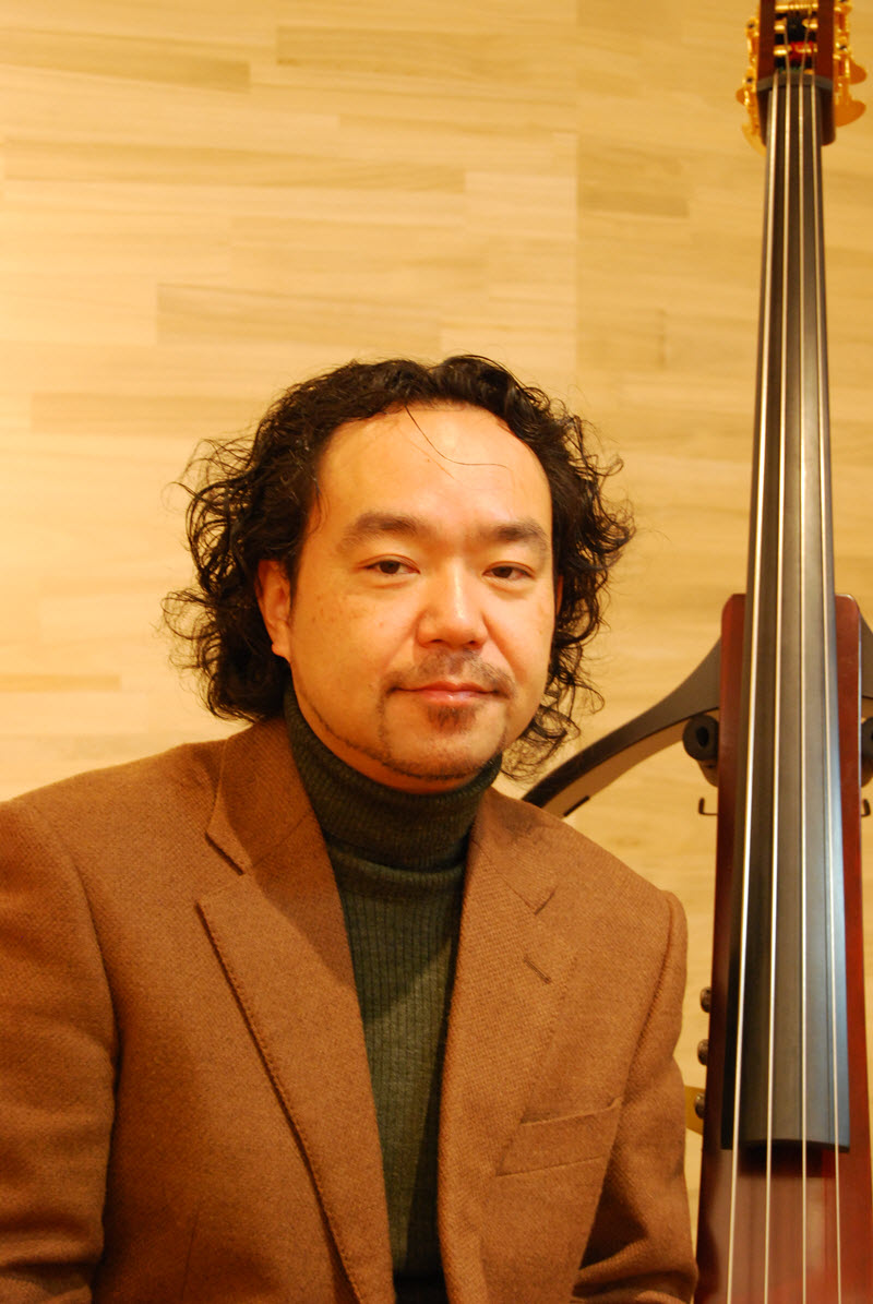
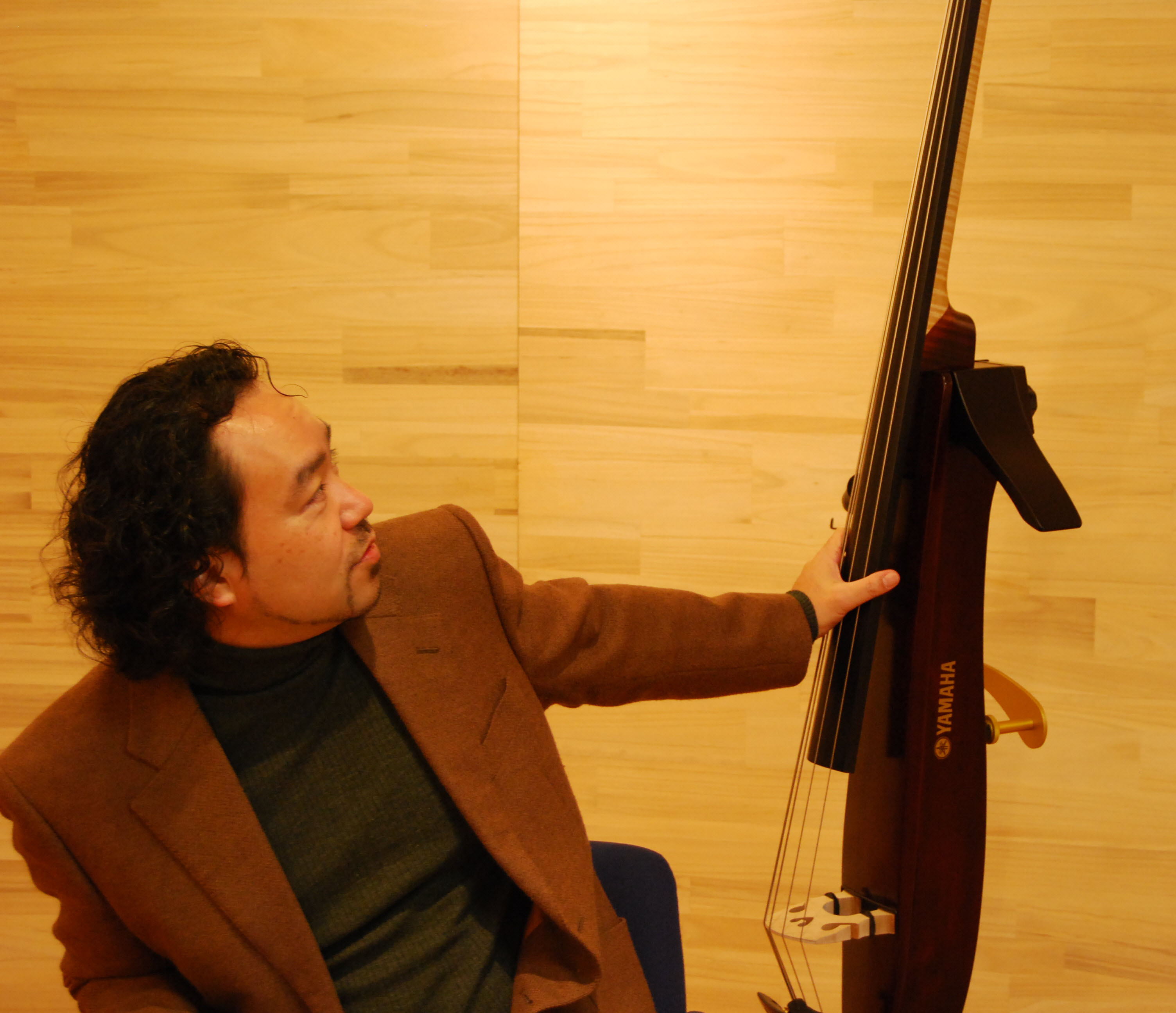
Have you ever wondered what goes into the design of a Yamaha instrument? How does a designer go all the way from concept to production? Here’s an interview that was recently conducted with Mr. Shinya Tamura, lead designer of the Yamaha SILENT Bass™ and SILENT Cello™ instruments.
Can you tell us about your background?
ST: I’ve been working on the development of the SILENT series of string instruments since I joined Yamaha in 1998. My first product at Yamaha was the SILENT Cello SVC-200. Following that, I was involved with the SILENT Bass SLB100 [SVB-100 in the U.S.], released in 2000. Because it was the first SILENT Bass we ever developed, I remember I worked like mad at the time, but it has become a good memory now.
How did the SILENT Bass come about?
ST: The SLB-100 was developed with the expert input of mainly classical music players. In contrast, the SLB-200 [SVB-200] was developed in 2004 under a concept of being more suitable for jazz. Working on these two projects gave me valuable opportunities to talk with various kinds of artists. Through this experience, I came to have strong aspirations to make a new product, and I believed I would be able to make one, blending professional ideas I had learned from those artists and ideas that had been gestating in my head. Finally my wish came true and I started to embark on the development of the SLB200LTD Silent Bass Limited Edition PRO.
What sort of challenges did you face in developing the Limited Edition PRO?
ST: I faced lots of things from the beginning. Playing it on its own, I had confidence that we had made a good instrument with nice sound. But then I showed our first prototype to [American jazz bassist] Chris Minh Doky in 2007 during his visit to Japan. When I asked him to play it in his band and I heard it from an audience seat, it turned out that the sound was too fat and didn’t carry well. So I asked Chris and his co-players for their opinions and also did further listening to develop an image of an improved instrument. To realize this image, prototyping was repeated again and again. During the course of development, we asked many bass players, including [Yamaha Artists] Nathan East and Tatsuya Ikeda, as well as Chris, to test play. We also tried various materials and parts, experimenting with different combinations.
When did you start to see an improvement?
ST: When we made some modifications to the bridge and circuitry based on the lessons learned from the first live test, I felt that the sound was improved one rank. After that, when I had Chris try the SILENT Bass again on his stage, I was convinced that it had improved. What’s more, Kevin Kaufman, a former bass technician with Jaco Pastorius who happened to be there at that time, praised the SILENT Bass a great deal, which made me really happy. That experience gave me confidence that we were going to make it.
What was the most important thing in the instrument’s development?
ST: Of course, improving sound quality is important in developing any musical instrument. We sought to get a tonal color close to the raw sound, like the sound of a contrabass with a pickup through an amplifier. But if you place too much importance on that, it could make the sound difficult to use on a live stage, which is not good at all. I think it is most important for an instrument to have a feel that makes you enjoy playing it and want to play it more, in addition to having a good sound. “Feel” is something you experience through your five senses, like the texture [of the fingerboard] you feel unconsciously while playing, the vibrations transmitted from the frame unit and the touch of the tuning pegs you turn. We bore this in mind all throughout the instrument’s development, including part selection such as tuning pegs and neck.
Do you think you achieved the feel you aimed for?
ST: I saw players keep playing our SILENT Bass while chatting with others after they finished their evaluation of the instrument. That meant they spontaneously liked it. So I guess I could say I achieved the playing feel I had aimed for. It feels pretty good to see that players keep touching our instrument; in other words, that they like it by instinct.
Do you have any thoughts about how SILENT series string instruments should be used?
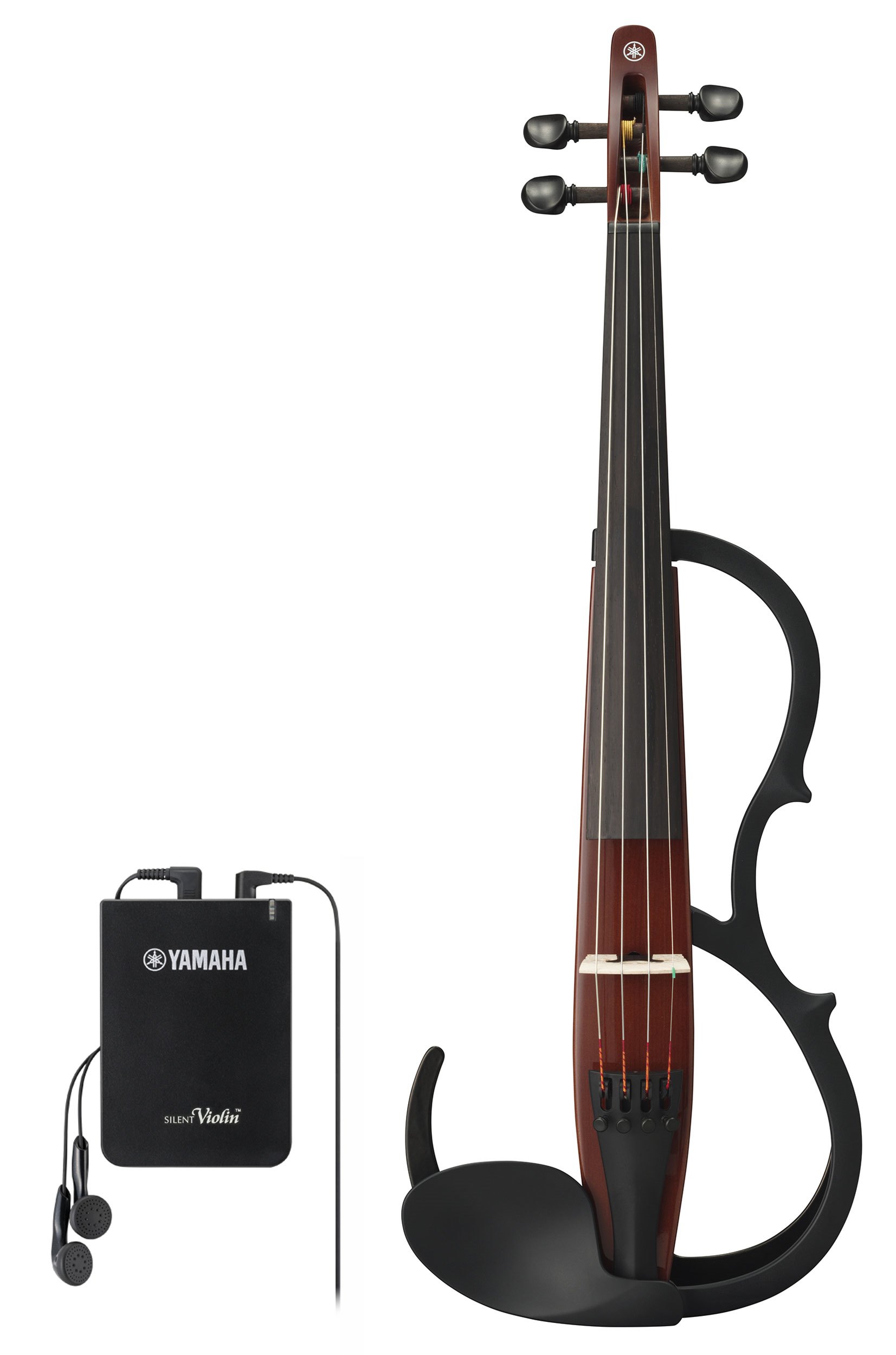
ST: The SILENT Violin was initially developed to allow a player to practice in a small house in Japan, so people said that it would not be in much demand abroad. But when it was released in overseas markets, it became popular for a different purpose – they used it to make the sound louder on stage. As to this SILENT Bass especially, we had a strong wish from the start of its development that it be played onstage, so I want musicians to not only practice it alone but play it in front of others. Because it has other advantages, such as easy home recording, I’d like to see it used in other ways, too, such as recording the heavy low register – something that is unique to the SILENT Bass – and uploading those recordings to the internet. I think musicians will be able to find new genres or musical possibilities by using a SILENT Bass instead of an upright bass or electric bass guitar, so I would strongly encourage players to try it in various ways.
The piano that Bartolomeo Cristofori first invented in Italy had only 54 keys. As piano music developed and evolved, this was gradually expanded in response to requests from composers who sought a broader potential for expression.
By the 1890s, today’s modern keyboard had become established with 88 keys spanning 7 ¼ octaves. These produce frequencies from 27.5 Hz to 4,186 Hz (4.186 kHz) when A is tuned to 440 Hz. (The pitch of the individual keys will vary depending on the tuning method.)
The human ear can hear sounds in the range from approximately 20 Hz to 20,000 Hz, but the upper limit of frequencies that the human brain can discriminate is at the very most around 4,000 Hz. Even if the range was to be expanded by increasing the number of keys on the piano, the extra notes at the bass end would, to the human ear, sound like nothing more than a rumbling noise, and the added treble notes would be heard as an unpleasant dissonant noise with no sense of being in a tonal range, and thus, musically, would be almost meaningless.
It’s true that, today, some manufacturers are making 97-key pianos to special order, with nine additional keys at the bottom of the keyboard. However, the strings for these nine keys are really only there to provide a richer sound when other keys are played by resonating along with them. In reality, the extra keys themselves are almost never played directly.
And now you know why most pianos have only 88 keys!
This is the third and final installment of a three-part video series called “Yamaha Revstar: Meet Your Other Half.”
Here’s a cool video in which musician Twin Shadow recalls his early experiences with guitar – taking one from his father’s closet whenever his dad wasn’t home – and gives us a look into the solitude afforded by his motorcycle journeys to Big Bear, California. “It’s important to remind yourself how important it is to take a step back sometimes,” he reflects.
“Learning how to play music has dictated the entire path of my life,” Shadow adds. “It puts you in the gang, this club of people that have a way of communicating with each other that [non-musicians] don’t have … [Music] is about elevating people and being elevated.”
He also shares his thoughts on his custom Revstar: “This guitar reminds me of a lot of different guitars that I’ve had throughout my life … [It’s] my tool for my vision, for my ideas.”
At the end of the day, isn’t that what all guitarists are searching for?
Miss the first two parts of this series? No problem! Click here for Part 1 or here for Part 2.
Click here to find out more about Yamaha Revstar guitars.
Have your students ever wondered why a piano has 88 keys instead of 89 or 90? Have they asked you which instruments are easy to play, and which are difficult? Are they curious about the components of a drum kit, or the difference between an acoustic guitar and an electric guitar?
Now there’s a comprehensive online resource for music educators and students that answers those questions, and many more.
The Yamaha Musical Instrument Guide offers detailed descriptions of 21 of the most popular instruments, with a wealth of information that includes the origin of each, along with its components and physical construction, as well as playing techniques.
But that’s not all. You’ll also find fingering charts (many of them downloadable), advice about choosing the best instrument, and tips for care and maintenance. There are even a variety of trivia questions for each instrument – little-known facts that lift the veil of mystery and add to the appreciation of music – along with hands-on exercises that will keep your students engaged and excited about the world of musical instruments and the sounds they create.
The instrument categories covered in the Guide are:
Note: This is the second installment of a three-part video series called “Yamaha Revstar: Meet Your Other Half.”
In this video, Andrew Aged of the band “Inc. No World” gives us a behind-the-scenes glimpse into his life, his home and his studio. He also shares his memories of the beginning part of his journey. “As a kid I saw a guitar in a music store and I just had to have it,” he recalls. “I asked my dad and he got it for me, and literally since the moment I got it I’ve never stopped.”
Recently, Aged started playing a custom Yamaha Revstar. His thoughts? “This guitar is responsive and precise, which I really like. It’s like driving a faster car than I’m used to!”
Like most musicians, Aged has his reflective side too. “I prefer to communicate musically because it’s abstract,” he says. “Words get in the way, no matter how hard we all try.”
“The thing about the guitar,” he adds, “is that it kind of removes a certain part of the intellect in the mind, at least the way I hope to play – it’s coming from the heart and there’s a sincerity about it.”
Aged concludes with a word of advice for up-and-coming guitarists: “You’ve got to put in the work; you’ve got to put in the time and the energy – then you’re able to get out of the way.”
(This is the third installment in our four-part series about brass mouthpieces.)
In Part 1, we talked about choosing the right mouthpiece for your needs.
In Part 2 we explored the mouthpiece cup and rim, which frequently get the most attention because they are the parts you can easily see and feel. However, the size and shape of the interior of the mouthpiece – the throat and the backbore – also have a huge impact on the way a brass instrument sounds and plays. Let’s take a closer look.
Throat
The throat is the opening at the bottom of the cup and is the narrowest part of the entire mouthpiece. All of the air you blow into your instrument is compressed and funneled through this tiny hole, so it focuses the energy you produce from the vibration of your lips before it moves into the instrument. The diameter and length of this part of the mouthpiece have a major influence on how much resistance you feel while playing. A narrow, long throat creates a lot of resistance which contributes to a fast response, brilliant tone and enhanced playability in the high register. A wide, short throat makes it easier to play low notes and can produce a large volume of sound, but will require more air from the player. If the throat is too large, you may find yourself tiring quickly.
Backbore
The backbore starts where the narrow part of the throat begins to widen. It runs all the way to the end of the mouthpiece, and may be given a complicated shape to help create a specific sound. Like the throat, the diameter and shape of the backbore have a big influence on both the tone produced and the amount of resistance you feel when playing. It’s probably no surprise that a narrower backbore will help with high notes, create a brighter tone and increase the overall resistance, while a more open backbore will make lower notes sound better and yield a darker tone.
Most Yamaha mouthpieces use a standard backbore shape that’s balanced to match the other characteristics of the mouthpiece to produce the appropriate sound. Models that are used for playing in the upper register are built with a tighter backbore to help you reach those high notes. The model numbers for these mouthpieces all end in the letter ‘a’ – for example, the trumpet mouthpiece 14A4a has a shallow cup and a narrow backbore, making it very popular with lead players.
In Part 4, we discuss how the weight of a mouthpiece and the materials it’s made from impact the sound and feel.
Click here to learn more about the extensive lineup of Yamaha mouthpieces.
Note: This is the first installment of a three-part video series called “Yamaha Revstar: Meet Your Other Half.”
Here’s a very cool video featuring solo artist Twin Shadow and Andrew Aged of the band “Inc. No World” – neither of whom had met before this day – coming together for an improvisational session with their Revstar guitars. The good vibes they create as they share in a melding of thought and creativity demonstrates the powerful role that guitar can play as an extension of one’s self.
We’ve all heard that firmware updates are crucial for every piece of electronic equipment we own, from our smartphones to our Wi-Fi® routers and everything in between. But what is firmware, really?
Firmware refers to the background program that runs a particular device. Basically, it’s software that is specifically designed for a piece of hardware. Sort of like “software for hardware.”
Unlike regular software — which are the programs that handle broad tasks like communicating, gaming and record keeping — firmware has a narrow purpose. It’s specifically written to address particular issues for one — and only one — piece of hardware.
Usually, you will only need to update firmware when the manufacturer sends out a notice to do so. Like all your other electronic equipment, your Yamaha AV receiver has firmware that may need to be updated from time to time.
Network Receivers
If you’re using a Yamaha network receiver that’s connected to your home Wi-Fi network, you’ll periodically receive an automatic notification on the front panel telling you that a firmware update is available.
When you see that notification, simply select “OK” on the on-screen display menu using the ENTER button on the remote. Wait a moment or two for the software to be downloaded and that’s it – you’re done!
Older or Non-Network Receivers
But what if your receiver is older or not a network model? Are firmware updates even available for such receivers? And how do you access them?
It’s simple – all you need to do is download the firmware update online. Here’s how to do it:
2. Once you’re on the product page for your specific receiver, click on the Downloads tab. If there are firmware updates available for your model, you’ll see a section called “Firmware / Software.” If it’s been a while since you’ve checked, you may find several updates listed – choose the most recent version.
3. Connect a standard USB thumb drive to your computer and download the firmware to it – a process that usually takes just minutes. Once that’s done, remove the thumb drive and plug it directly into the USB port on your receiver.
4. Power off your receiver. Then press and hold the STRAIGHT button on the front panel. With your finger still on the STRAIGHT button, press the Main Zone power button:
Keep your eye on the receiver’s display screen. Once you see the words “Advanced Set Up” appear, you can let go of the STRAIGHT button, then release the power button.
5. Press the PROGRAM left or right buttons on the front of the receiver until the display shows “Update USB.”
6. Press the INFO button on your receiver to start the update process. Have a little patience (or a cup of coffee) — it can take up to 20 minutes for the update to install.
The update goes through different stages. When it gets to the end of stage six, the process is complete – look for the on-screen display to say “Update successful, please power off.”
Enjoy Your New Features
Once you power your receiver off and then power it back on, you’re all set.
Now just sit back, relax and enjoy the great new features and increased functionality your firmware update delivers.
(This is our 100th blog posting … and it’s a special one!)
Company founder Torakusu Yamaha
On July 15, 1887, the principal of an elementary school in the remote city of Hamamatsu, Japan summoned a young watchmaker / medical equipment repairman named Torakusu Yamaha. Torakusu was asked if he could fix the school’s beloved reed organ, and he agreed to give it a try.
He was successful.
The principal of the school, one assumes, was delighted.
There and then, a company was born.
The Early Years
Encouraged by his success and recognizing the need for quality musical instruments, Torakusu began creating a prototype reed organ of his own. When it was complete, he decided to present it in person to the prestigious Music Institute (today’s Tokyo National University of Fine Arts and Music). The journey between the two cities at that time was a long and difficult one: Torakusu literally slung his creation over his shoulder on a carrying pole and crossed the mountains of Hakone on foot. This historic trek was later immortalized in the bas-relief shown here.
Reed organ assembly on the Nippon Gakki factory floor
But the organ was not well-received – in fact, it was criticized harshly for its poor tuning. Undaunted, Torakusu began studying music theory in order to master the art of tuning. After months of grappling with technical obstacles, he was finally able to construct an organ with reliable tuning. Later that same year, Torakusu established the Nippon Gakki Company (which, in English, translates to “Japan Musical Instrument Company”) and started producing portable reed organs. By 1889, the company employed 100 people and manufactured some 250 instruments a year.
In 1899, Japan’s education ministry sent Torakusu to the United States to learn piano making. Nippon Gakki began manufacturing upright pianos in 1900, followed by grand pianos starting in 1902. In 1914, the company introduced their first harmonica and began exporting them worldwide.
Diversification into New Areas
In the late 1940s, Genichi Kawakami, then-president of Yamaha, began looking for ways to apply the company’s expertise to the manufacture of motorcycles. In 1955, the success of the YA-1 “Red Dragonfly” resulted in the founding of Yamaha Motor Co., Ltd. At around the same time, Nippon Gakki began research into the use of new materials such as glass fiber reinforced plastic, resulting in products such as sailboats, yachts and oceangoing fishing vessels, as well as bows for archery and skiing – even bathtubs! That same research led to the development of lead alloy production equipment for boilers and central heating systems.
Audio Comes of Age
The Yamaha CA-1000 audio amplifier
Despite the worldwide success of Yamaha Motors, the central theme of Nippon Gakki remained true to its founder’s central interest: music. During the “Hi-Fi” boom of the 1950s, the company began producing audio components to help music lovers enjoy their leisure time. When integrated circuits began replacing transistors in the early 1970s, Nippon Gakki started making their own in order to meet the rapidly increasing demand for electronic keyboards and audio devices. In 1976, a factory to produce large scale integrated circuits was opened; soon thereafter, all Yamaha electronic keyboards were converted from analog to digital format. Not coincidentally, that same year saw a spate of new product releases, including the first Yamaha electric piano and synthesizer.
An Era of Rapid Expansion
The 1980s were a time of growth for Yamaha. In 1982, the Disklavier™ was unveiled – a revolutionary product that combined an acoustic piano with a built-in computer to record and play back performances. The DX7 digital synthesizer, introduced in 1983, quickly became the world’s best-selling synth. In 1987, Yamaha released its first digital mixer, followed in 1989 by the world’s first CD recorder.
The Yamaha DX7
This was a trend that would continue. 1993 saw the introduction of the first of the innovative SILENT™ series – a piano that could be heard normally, or through headphones only. This was later followed by other SILENT instruments, including trumpet, drums, violin, cello, bass, guitar and viola. In 2009, Yamaha debuted the world’s first hybrid piano – an all-digital instrument that replicates the touch and feel of an acoustic piano without the cost or maintenance.
In addition, Yamaha has acquired a number of other leading companies over the years, including piano manufacturer Bösendorfer; software developer Steinberg; and Line 6, maker of digital modeling guitars and amplifiers.
Yamaha Today
In 1960, Nippon Gakki established the Yamaha International Corporation (later renamed Yamaha Corporation of America). Today, Yamaha is the world’s largest manufacturer of musical instruments, as well as a leading manufacturer of semiconductors, AV components, computer-related products, sporting goods, household and furniture products, specialty metals, machine tools and industrial robots. Yamaha also continues its pioneering research in modern technologies such as the application of artificial intelligence to music-making and live performance.
Anatomy of a Logo
In 1898, Nippon Gakki adopted a tuning fork as the basis for an official company logo, inspired by the challenge faced by founder Torakusu Yamaha as he struggled to refine his reed organ prototype into one that held its tuning.
The three tuning forks of the modern Yamaha logo symbolize the three essential musical elements: melody, harmony and rhythm. They also evoke the company’s reputation for sound and music the world over – a territory signified by the enclosing circle. After all, music is the universal language!
For more information about the history of Yamaha, check out the video below:
Milestones
Here are a few milestones in the history of Yamaha:
1887: First reed organ 1900: First upright piano 1902: First grand piano 1914: First harmonica 1915: First xylophone 1932: First pipe organ 1954: First Hi-Fi player 1959: First electric organ 1966: First acoustic guitar; first electric guitar; first electric bass; first guitar amplifier; first trumpet 1967: First recorder; first saxophone; first marimba; first acoustic drum set; first loudspeaker 1969: First trombone; first tuba 1970: First French horn; first flute; first clarinet; first euphonium 1972: First audio mixer; first integrated amplifier 1974: First alto horn; first power amplifier; first headphones 1975: First preamplifier 1976: First electric piano; first synthesizer 1979: First portable keyboard 1982: First CD player 1984: First marching drums; first timpani; first sequencer; first MIDI keyboard controller 1985: First multi-effects processor 1986: First oboe; first rhythm machine; first electronic drum kit 1987: First Disklavier™; first bassoon; first MIDI wind controller; first digital mixer 1991: First AV receiver 1993: First SILENT Piano™ 1995: First SILENT Brass™; first home theater surround system 1996: First SILENT Session Drums™ 1997: First SILENT Violin™ 1998: First SILENT Cello™ 2000: First violin; first SILENT Bass™ 2001: First SILENT Guitar™ 2002: First SILENT Viola™; first Arranger workstation 2004: First digital sound projector 2008: First audio interface; first pocket recorder 2009: First hybrid piano
Recorders are a fun and accessible first instrument that’s easy to learn and play. In fact, it’s safe to say that the simple recorder is one of the most common musical instruments on the planet, with millions of children around the world learning to play music on a recorder every year. However, it can be confusing to know what type of recorder to use, especially since there are two different fingering systems to choose from. Here’s some history and an explanation that will hopefully help clear up the mystery.
Baroque Recorders
Instruments similar to the recorder have existed for many hundreds of years – and probably even longer. These instruments evolved over time, reaching a peak of design and popularity in the 1600s and early 1700s, also known as the Baroque period of music. While modern recorder designs have continued to develop, most of the instruments you can buy today share many of the fundamental features of those Baroque-era designs.
German Recorders
In the 1920s, instrument designers in Germany felt that the standard Baroque recorder was too difficult for beginners to learn, since some notes put the player’s fingers in positions that can feel uncomfortable or unnatural. Because of this, they made a small change to make those notes easier for a beginner to play. However, there was a trade-off – while the finger positions were easier, some notes became harder to play in tune.
Telling Them Apart
You can easily tell which type of recorder you have by comparing just two tone holes. If you look at the holes on a traditional Baroque recorder, the fourth hole down from the top is smaller than the fifth hole. On a German recorder, the order is switched – the fourth hole is larger than the fifth hole. That’s all there is to it! (You can find more information about the differences between the two here.)
Which One to Use?
Most schools today teach the traditional Baroque system and will expect students to use a Baroque recorder such as the Yamaha YRS-24B. If you happen to have a teacher or class that does teach the German system, then a model like the Yamaha YRS-23 would be the one to use. If you’re not sure, it’s always best to ask the teacher. Otherwise you might end up playing some of the notes wrong!
If you’re playing by yourself for fun, either style is OK. You can play the same music with both types, so use whichever you prefer. However, if you’re a serious recorder player you may find that the improved tuning of the Baroque system is better in the long run.
Click here for more information about all the different types of recorders that Yamaha offers.
Player pianos have come a long way since the days of providing music in the saloon! Join pianist and music educator George F. Litterst in this three-part video series as he takes you through the main features of the Yamaha DisklavierTM PRO.
This installment provides a comparison between the standard Disklavier and the Disklavier PRO, along with a description of the many advantages offered by today’s models:
If you missed the first two videos, check them out here:
Have you ever heard the term “gray market piano”? Many people shopping for pianos may come across this phrase when doing research online or speaking with a dealer. Shopping for a new piano can be a daunting task, and if you have little (or no) experience buying one, it can be easy to be misdirected by sellers offering gray market pianos – instruments purchased in large quantities in Japan or other Asian countries, packed into shipping containers, and then brought into the United States for resale. They may be great instruments in excellent shape – and they often come with an attractive price tag – but before you jump at the opportunity to buy one, there are a few things you need to know:
1. You may be looking at major repair problems down the road. Only a handful of piano makers, including Yamaha, build pianos specifically for the three major world markets: Asia, which is a moist climate; Europe, which is fairly dry by comparison; and the U.S., which is considered to be extremely dry. (Keep in mind that we are talking about the INDOOR climate, as opposed to outdoors.) In winter, heating systems remove substantial moisture from the air, and in summer, air conditioning systems also lower the humidity. In addition, American homes tend to be better insulated than homes in many other countries, further isolating the interior from whatever moisture might be in the outside air.
The problem is that, when a piano that’s intended for a moist climate is placed in a dry environment, there is the likelihood that its structural integrity will be threatened as the wooden parts lose moisture. This in turn can cause warping of case parts, cracks in the soundboard and/or loose tuning pins. And while soundboard cracks are often only cosmetic in nature, loose tuning pins will have a direct effect on the ability of the piano to hold its tuning. If that happens, the only practical solution is to re-pin the piano with oversized tuning pins – a procedure that typically comes with a fairly high price tag, since it often encompasses re-stringing the piano too. That’s why, when Yamaha builds pianos destined for the U.S., it seasons the critical wooden components – including the soundboard, bridges, ribs and pin block – by drying them to a much lower moisture content using computer-controlled kilns and other advanced manufacturing technologies.
2. Lack of warranty. There is absolutely no factory warranty coverage on gray market pianos, so if you ever need any of the (likely, and likely expensive) repairs cited above – or any other repairs, for that matter – you’re strictly on your own.
3. “New” may not really be new. Many gray market pianos represented as “new” are actually used pianos that have been reconditioned by independent piano shops. Others have been sold to third party entities, who then ship the products into the U.S. for unauthorized sales.
4. Replacement parts can be difficult to find. It’s always a good idea to verify the true origin and backstory behind any major purchase. You wouldn’t buy an existing house or a used car without trying to learn all you can about its history, would you? The unfortunate reality is that you won’t ever truly know everything about a gray market piano, ranging from its cabinet style and finish to its year of manufacture and/or internal components. There are many models and styles of piano built for other areas of the world that are quite different from those sold in the U.S. As a result, finding parts can become a rather complicated affair for the owner of a gray market piano since even the manufacturer may be unable to assist you.
If you or someone you know is being offered a gray market Yamaha piano, or if you want to verify whether or not your Yamaha piano was built for use in the United States, you can use our free serial number finder tool available here.
For the past 27 years, Yamaha has been the presenting sponsor of Music for All, an organization that has brought life-changing music education and performance opportunities to generations of band and orchestral students since its founding in 1975.
Player pianos have come a long way since the days of providing music in the saloon! Join pianist and music educator George F. Litterst in this three-part video series as he takes you through the main features of the Yamaha DisklavierTM PRO.
Legendary pianist Arthur Rubinstein once said, “The more I play, the more convinced I am the pedal is the soul of the pianoforte!” In this video, George Litterst describes how the Disklavier PRO accurately records and plays back pedaling motion – not just of the damper pedal, but the una corda pedal as well – and explains why incremental pedal data is so important.
Custom installers spend hours carefully measuring, evaluating, analyzing and adjusting the audio settings on home theater systems so they sound just right. YPAO™ Sound Optimization by Yamaha delivers similar results in less time than it takes to decide what movie to watch. In just minutes, it automatically analyzes the acoustics of your listening and viewing space so that the sound you hear is the absolute best it can be. It’s as if a custom installer has set up and calibrated your entire system – the results are that good.
Best of all, it doesn’t matter if the room is a cavernous space with soaring ceilings or a 10′ x 10′ bedroom that’s been converted into the kids’ “media room” – the technology works the same way.
The Magic Starts Here
Featured in the majority of Yamaha receivers, YPAO uses sophisticated digital processing to work its magic, starting with the provided YPAO microphone. The receiver generates a series of high and low sounds, which are actually specially devised test tones, and plays them through your connected speakers. The microphone then picks up these test tones and sends them to the processor for analyzing.
Place the YPAO microphone on a stable surface at ear level, near where you will be doing most of your viewing and listening. Try using a tripod.
The receiver then measures and sets speaker levels, adjusts speaker delays and matches the timbre of the speakers to each other, optimizing your system settings and listening environment.
Reduce Reflections
Furniture and walls close to the speaker can have a “muddying” effect on sound clarity. YPAO employs a special Reflected Sound Control to reduce their impact, producing even, high-resolution sound.
YPAO Volume
As an added bonus, YPAO-equipped receivers also provide a feature called YPAO Volume. As described in a previous blog posting, this applies loudness equalization to the audio that passes through your AV receiver. The result is improved clarity and balanced low, mid and high frequencies at all volume levels.
In 2016, Yamaha ushered in a new era of sonic exploration with the introduction of MONTAGE.
Building on the legacy of the industry-changing DX and the hugely popular Motif, MONTAGE synthesizers combine sophisticated dynamic control, flexible sound creation and a streamlined workflow in a powerful keyboard designed to inspire creativity.
Whether you’re new to MONTAGE or a veteran user, we’ve got resources galore for you.
MONTAGE Videos
Love learning online? You definitely want to check out the Mastering MONTAGE video series. Here you’ll find over four hours of video content, all completely free of charge. These range from “MONTAGE 101” – six videos that cover basic user interface controls and navigation – to advanced topics such as interfacing MONTAGE to Cubase via both MIDI and audio.
FM-Related MONTAGE Articles
The MONTAGE’s FM-X engine is a powerful tone generator that offers a huge and diverse palette of sounds, and the touch screen user interface – coupled with physical controls – provides extensive editing capabilities. You can explore all this in detail in our four-part series of articles entitled “Mastering MONTAGE: An FM-X Exploration,” authored by Phil “Bad Mister” Clendeninn.
In Part 1, Phil introduces some of the features that make FM-X so powerful, explains the basic difference between a carrier and a modulator operator, and talks about how the influence of a modulator on a carrier adds brightness and harmonics to the sound.
Part 2 highlights the real time control possibilities of FM within MONTAGE. In this article, Phil assigns FM parameters to each of the MONTAGE’s eight assignable knobs and describes in detail what each parameter is controlling.
Part 3 provides an even deeper exploration of the carrier/modulator relationship – the fundamental building blocks of FM synthesis. Here Phil explores different operator waveform spectra and demonstrates how the MONTAGE’s Super Knob can be used to dramatically alter the timbre of the sound as you play.
Finally, Part 4 puts all the pieces together with a detailed description of how to create a multi-part “Moving Floor” Performance.
For more information about MONTAGE and our other synthesizers, visit the yamahasynth.com website.
Player pianos have come a long way since the days of providing music in the saloon! Join pianist and music educator George F. Litterst in this three-part video series as he takes you through the main features of the Yamaha DisklavierTM PRO.
Here he explains how the Disklavier captures key release velocity with the use of highly sensitive key and hammer speed sensors:
For more than four decades, Yamaha Corporation of America has partnered with the Monterey Jazz Festival (MJF) to provide world-class instruments for the festival’s multiple stages and rehearsal areas, as well as support for the organization’s many educational programs designed to nurture and develop young jazz musicians. As the official supplier of drum sets and pianos during the three-day festival, Yamaha helps ensure consistent and exceptional sound quality for performers and concertgoers alike.
The MJF is the nation’s oldest continuous running jazz series. Throughout its long history it has brought thousands of artists from across the globe to create musical magic amid the beauty of the Monterey peninsula. The Festival attracts an audience of over 36,000 and features a line-up of hundreds of artists, showcasing the best jazz has to offer and performing on everything from a Yamaha CFX concert grand piano to Absolute Hybrid Maple drums.
In addition, an annual Jazz Legends Gala benefits MJF’s numerous jazz education programs, including Monterey Jazz in the Schools, Next Generation Jazz Festival, Next Generation Jazz Orchestra, Summer Jazz Camp, Monterey County Honor Ensembles and the MJF Instrument Bank and Sheet Music Library.
Learn more about the MJF programs and festival in these videos:
Click here for more information about the Monterey Jazz Festival.
In Part 1 of this three-part series, we talked about the general differences between an acoustic drum set and an electronic one – and in Part 2 we focused on the acoustic variety. Let’s wrap things up with a detailed look at electronic drums.
Cost Versus Quality
If you’re shopping for electronic drums, you’ll find that the market is full of low-cost options. But remember, your child will be physically hitting the drums and many cheaper kits will fail over time due to heavy use. More expensive electronic kits tend to be more robust, feel more realistic and offer larger playing surfaces similar in size to those found in an acoustic drum kit. For beginning students, look for an electronic drum set that is priced similarly to a good quality, entry-level acoustic one – it will offer better value as well as a variety of great sounds for your child to enjoy during their practice and learning.
Module
The module – sometimes known as the “brain” of an electronic drum set – generates the sounds that you hear when connected pads are struck. The quality of the chips inside the module play an important role in keeping your young drummer more engaged. The better the sounds, the more fun it is to play! Modules are sometimes advertised as having thousands of sounds, but keep in mind that quantity isn’t everything. The sounds should be useful, realistic and have an authentic “latency” (that is, the appropriate amount of time from the instant a player hits the pad to when the sound is heard). Creating lots of sounds that meet this criteria – without eating up memory – adds cost, so entry-level kits typically have fewer sounds.
You may also want to strongly consider purchasing an electronic drum kit that allows your child to edit and/or create their own sounds. Young students love to tinker!
Training Functions
One big advantage to electronic drums are the built-in training functions that allow the aspiring musician to improve the critical skills of timing and feel. This can include built-in songs the student can play along to, making training and practice more fun – and therefore ultimately more successful.
Drum and Cymbal Pads
There are several types of drum and cymbal pads available. When choosing, look for a good feel that pairs well with the sounds of the module. You can have a very good pad and an average module – or vice versa. To a certain degree, having one element of better quality may help enhance the capabilities of the other, but eventually you’ll find that the response of the pad is the most important factor.
Another thing to consider is the feel of the pads as compared to acoustic drums. Most likely, your child will be playing acoustic drums if they end up performing in school or other live settings. Look for pads that have a rebound that’s similar to acoustic drums and traditional practice pads. Unlike acoustic drum heads, electronic pads tend to have a similar feel from one to the next. As a result, rubber pads are generally used in less expensive starter electronic drum sets, although some may offer mesh or foam.
Rack/Hardware
Racks or stands are used to hold electronic drums in place and are an important part of the playability factor. Small racks tend to be used for smaller pads and so the spacing can be very different than that of an acoustic drum set, making for a dissimilar experience. Electronic drum sets like these can take time to feel natural, especially if moving between acoustic in performance and electronic for practice. Large racks, on the other hand, can accommodate larger pads, making the spacing much more realistic. This in turn gives the student a more authentic practice experience. Spacing can influence the kit’s durability too, since allowing proper playing position and being able to keep things stable once the kit is set up (as opposed to constantly loosening and tightening knobs) can cut down on the wear and tear of the mounting hardware.
Some Things to Consider in an Electronic Kit
1. Sounds: There’s usually a direct relationship between the price of a module and the quality and variety of sounds it offers. Top-notch modules include all the standard drum set sounds you would expect, but also offer many other instruments such as bells, wood blocks, special effects, non-percussion instruments and much more. High-end modules also allow you to edit and create your own sounds, and in some cases, allow you to download your own samples. Modules with download capabilities can cultivate creativity! 2. Preset patterns: Every module has a selection of preset patterns, typically, short two-bar patterns or drum parts related to specific drum kits or musical styles. As mentioned earlier, these can be valuable learning tools, as well as a source of inspiration in creating your own unique drum parts. Many modules include full play-along tracks for both fun and practice. 3. Connectivity and expansion: If you plan to expand your child’s electronic kit with more pads and triggers in the future, be sure the module has enough connectors to allow this. A USB port lets you send MIDI data to external PCs, digital audio interfaces and workstations – giving you access to a wide range of music software. Audio inputs for connecting MP3 or CD players let you practice and play along with your favorite music. Multiple outputs that can send your performance simultaneously to a mixer and recorder can be useful in both live and studio settings. Also, be sure that the outputs will support the type of amplification system you plan to use.
Features to Look for in an Electronic Kit
1. A module that is simple to use and sounds well: It should also allow you to download new kits and customize existing kits with fresh sounds and capabilities. There’s no better way to keep your child engaged! 2. Pads that are sturdy and have a good feel when played: They should have some give, but not too much rebound or bounce. 3. A rack that has sufficient weight to keep things in place yet easy to adjust: The mounting hardware of your electronic drum kit should make it easy to keep components in place, using a standard drum key or knobs that stay tight. 4. Durability: Anything your student hits with a stick should have some mass – and feel sturdy.
Things to Avoid in an Electronic Kit
1. A module with significant limitations: If it doesn’t allow you to personalize the feel of the kit or limits the number of pads you can add (due to only a few or single-zone inputs), keep looking. 2. A module that has poor sounds: Unlike acoustic drums, you can’t fix the sounds of an electronic kit with well-placed tape or muffling. 3. Pads that feel too hard: This can can cause fatigue for younger hands. 4. Pads that feel flimsy: Typically, these will not hold up under normal playing conditions – especially at the hands of a child. 5. Pads that are too bouncy: These can make transitioning to an acoustic drum kit difficult.
That about wraps it up for electronic drums – and our series. If you haven’t had an opportunity, check out Part 1 and Part 2 of this three-part series for more information.
Good luck to you and your burgeoning young drummer!
Click herefor more information about Yamaha drums.
Here are some links that can augment your understanding of the music industry and help you identify key trends, including: details on student enrollment; demographics and projections relating to educational funding, school construction and teacher population; and key economic indicators that affect the business of music.
These are also good listening topics for your students. Look them up on iTunes® or any other Podcast app service:
– NPR
– Talking up Music Education
– Marching Roundtable
– Marketing Music Education
– TED Radio Hour
Email Lists
We all get too many unnecessary and unwanted emails. Here are four email subscriptions worth having. These are all free and provide current info about arts education:
One of the great pleasures in life is enjoying a favorite movie in the comfort of your own home. For many people, that’s the only way they watch movies. Who needs the crowds of the multiplex, the distracting glow of cell phones, the people talking in the row behind you – not to mention the ticket prices?
The Old Days: Wearing Out the Volume Control
The YPAO™ Dynamic Range Control (DRC) feature offered by many Yamaha AV receivers is one of the reasons that watching movies at home is better now than ever before. (“Dynamic range” refers to the difference between the softest parts of the audio and the loudest.)
Before this innovation, you often had to turn up the volume in order to clearly hear dialogue, especially during quiet passages. Then, mere seconds later, the scene would change and suddenly loud audio – dramatic music or an explosion – would come bursting out of the speakers, making everyone jump. Then, of course, you had to turn the volume down, only to have to raise it again a few minutes later when machine guns started chattering or bombs started flying. The annoyance factor was off the charts!
Getting It Right
YPAO DRC puts an end to all that. Featured in the entire line of AVENTAGE and RX-V series AV receivers, this advanced technology compresses the dynamic range of the sound track. It raises the volume of the quietest sounds to make them audible, while decreasing the volume of the loudest ones, resulting in a more comfortable listening experience.
Voila! No more startled jumps when the scene switches between whispered conversation and the lobbing of hand grenades. No more “Dang, these commercials are so loud!” complaints interfering with the enjoyment of your favorite TV show. With YPAO DRC technology, your sound is always perfectly attuned to you.
And better sound, of course, means better entertainment. No wonder more people than ever are watching movies at home!
In Part 1 of this three-part series, we talked about the general differences between an acoustic drum set and an electronic one. Here in Part 2, we’ll focus on the acoustic variety.
The parts of a drum set (sometimes called a drum “kit”) that your child will use most of the time are the bass (“kick”) drum, snare drum, hi-hat and ride cymbal. These are the basic components of any groove and are therefore the focus of most beginning lessons. A starter drum set may also include one or more crash cymbals and several tom-toms. Typically, at least one small tom-tom will be mounted to the bass drum, in which case it is called a “rack” tom. Larger ones may be freestanding, in which case they are called “floor” toms.
Drum Sizes
Beginning drum sets usually come in standard drum sizes. The snare drum will typically be 14″ in diameter; rack toms will be 10″ or 12″; floor toms will be 14″ or 16″; and the bass drum will be 20″ or 22″. The only real consideration here is that if your child is short, a 20″ bass drum is probably a better choice, since any rack toms mounted to it will be easier to reach. (There are 18″ bass drum options also available but the larger sizes have a more standard tone and tend to be better suited for a variety of different types of music.)
Smaller drums are typically tighter and higher in tone, with more of a controlled sound; while larger drums resonate more and generate lower tones. Your child should be able to play any style of music on a well-constructed acoustic kit.
Shell Types
There are many types of hardwoods used by drum manufacturers. The most common found in entry-level kits are birch, maple and poplar. While most woods are capable of creating a good tone, the construction of the shell will determine how easy the drum is to tune, as well as the sound quality at various tuning ranges or dynamic levels.
Drum Heads
Standard drum heads on entry-level kits tend to be inexpensive and need to be replaced after a short time. They may be durable enough to get you started, but in many cases, changing the head to a better quality one can improve the sound of an average drum. Additionally, a higher quality replacement head will wear better and last longer than the original that came with the kit.
Cymbals
This is an element you want to make sure sounds just right when you purchase it! Unlike a poor-sounding drum that you can improve by applying tape or changing the heads, there’s little you can do to change the tonality of a cymbal. Good cymbals will have definition and a warm tone. An entry-level drum set will typically include a pair of thin 14″ hi-hats (cymbals that are mounted horizontally on a stand so that they come in contact with one another with varying pressure as a foot pedal is pressed), a medium-weight 18″ or 20″ ride cymbal, and sometimes a lightweight 16″ crash cymbal too. Many players opt to add a second crash, though this is less commonly found in starter kits.
Hardware
Hardware starts with the bass drum pedal and the hi-hat stand – these can impact the experience of playing the drums as they act as extensions of the feet. Good hardware is not only easy to adjust, it holds up better when traveling. The metal should not bend when adjusting, nor should it lock up after use. Beware of peeling chrome and sharp metal edges. Even lightweight stands should have a sturdy feel. If they tip easily, or are difficult to position, they will only get more difficult to work with as they age.
Drumsticks
This is a another element that needs to be good from the start – you can’t make bad sticks better. Make sure the size is appropriate for your budding young drummer. The 5A is a good starting point for most students; as they begin to develop various musical styles they may want lighter or heaver sticks. In order to prevent injury to both themselves and their drum set, avoid giving developing students sticks that are too large or too heavy.
Drum Key
As discussed in Part 1, this small device is used to tighten the drum heads and raise them up or down in pitch. Most drum sets – even those for beginners – will include such a key. Thankfully they are inexpensive and universal in size, so they’re easy to replace if lost!
Things to Look for in an Acoustic Kit
1. Mass: A good drum has some weight and feels sturdy. If the drum feels light, the metal and shell is a lower quality. While such drums are not necessarily bad, they are typically harder to tune and tend to need to be replaced sooner.
2. Expandability: If the skills and enthusiasm of your young drummer grow in future, make sure you can add extra components and order individual drums in the same color as your current set. Ask what sizes might be available.
3. Substantial features for your investment: Good drums, heads and hardware can cost a bit more, but they will also retain their value and make it easier to trade up when your child is ready.
Things to Avoid in an Acoustic Kit
1. Metal corrosion and poor workmanship: Examine the drum shell inside and out. Pay attention to the appearance of the seams. Are they well-crafted and without flaws? Is the finish smooth, with no “bubbling”? If the work is sloppy, chances are you’ll spend more time repairing or replacing things than actually playing the drums.
2. A manufacturer that doesn’t stand behind their instruments: Research drum brands ahead of time. Look for those that have gotten good reviews from users and/or impartial journalists. Lofty features and marketing claims are hard to substantiate without reviews! Things can break and get worn, but quality endures and is reflected in the way the manufacturer is perceived in the marketplace.
Safety First!
Because your child will come in contact with metal parts and wood that is glued in sheets, the proper manufacture of the drum set components you purchase will ensure the safety of your young musician. It’s particularly important that you inspect metal parts for sharp edges and plating that is not peeling or corroding.
That about covers it for acoustic drums. In Part 3, we’ll examine the electronic drum kit in detail.
Photo courtesy of Reverb.
Click here for more information about Yamaha drums.
Shopping for drums can be time-consuming and confusing for parents of a beginning music student. This three-part series provides a simple guide for making sure your child starts out with the right instrument – one that grows with them as they progress.
Lessons for Everyone
Teaching children how to play drums can be fun – and you might learn a bit about drumming, too – but to inspire them to the next level, you should investigate lessons and local teachers. Online lessons offer some great tips, but similar to coaching a golf or tennis swing, there’s no substitute for a real-life teacher who can provide on-the-spot guidance as a student learns correct stick movement and other fundamentals. Teaching proper technique is of critical importance in helping ensure that your child is not stressing muscles and creating unnecessary fatigue. One lesson can go a long way in improving the skills and concepts of drumming.
Have Fun!
The most important thing is to have fun! This is a great opportunity for you and your child to enjoy something exciting, creative and collaborative. Music may not be their career, but they can use these new-found skills to make and enjoy music for the rest of their lives.
Speaking of “fun,” let’s take a look at some of the fundamentals…
The Drum Set
A drum set (sometimes called a drum “kit”) is simply a collection of drums, cymbals and mounting hardware, similar to those you see played onstage by your favorite band. If your child is part of a school music program, they might be required to rent or purchase a bell kit, combo kit or drum pad. The fundamentals of percussion are typically taught on bells for note reading and on the snare pad or snare drum for rudiments of stick control. These rudiments are important. If you already have a bell kit or combo kit, your child is off to a good start. However, a drum kit will cost a bit more and require more space. Even if your child has not taken music lessons and has not joined the school band, not to worry – the articles in this series will provide you with all the tools you need to get them started.
A typical 5-piece acoustic drum set.
Student bell or combo kit with drum pad.
An acoustic drum set is made up of the following five basic components:
1. Drums: There are typically at least four or five drums in a set. Each consists of a shell (typically made of wood, but also sometimes metal), across which is stretched a drum skin or “head” (typically made of clear plastic Mylar® or calfskin) – the surface you hit with a stick. 2. Cymbals: Circular plates made of metal, used for a crashing sound. 3. Hardware: Metal stands to hold the cymbals and drums, plus a throne (seat), a foot pedal (for the bass drum) and a hi-hat stand that includes a pedal for crashing two cymbals together. 4. Sticks: Long wooden dowels used to strike the drums and cymbals. 5. Drum key: A small metal device used to tune the drums by stretching their skins.
Electronic drum sets contain only the first four components, although the “drum” and “cymbal” sounds are produced via electronic not acoustic means (more about this in Part III.) Whichever way you go, starting with good quality instruments will make the experience more enjoyable – and can save you money down the road.
Acoustic Drums or Electronic Drums?
When deciding which kind of drums to buy, one of the most important factors is the space required. In addition, you will want to consider the time of day your child will be practicing – will this disrupt you, your other family members or the neighbors?
Acoustic kits are the most common types used by school bands. They are much louder than electronic drums, have a much larger footprint and will require some sort of isolated room for practice.
Electronic kits are smaller, quieter and easier to use since you don’t have to worry about tuning or changing drum heads. An electronic drum kit is often the best choice for beginners since you won’t need to soundproof the room where they are located – your child can use headphones to practice.
Here’s a summary of the advantages and disadvantages of each:
Acoustic drums
– The standard for school lessons and live performance.
– Loud!
– Take them anywhere: not tethered to a power outlet.
– Instant gratification: nothing to plug in or set up. Just start hitting ’em!
– Good for larger bedrooms, basements or garage… especially if the spaces can be soundproofed.
– Produce one sound with various tunings.
– Drums and cymbals come in various sizes.
– Larger footprint: requires an average 5′ x 5′ space.
– Requires lots of new sticks and drum skins as they wear.
Electronic drums
– Easily used at home but requires amplification for performance.
– Quiet practice with headphones.
– Good for apartments or small bedrooms.
– Capable of producing various sounds and styles of drum kits.
– Requires some setup and an electrical outlet.
– Pads for drums and cymbals are typically smaller than their acoustic counterparts.
– Smaller footprint: requires only an average 4′ x 4′ space.
– Built in training functions and metronome.
– Less stick wear and no heads to tune or replace.
In Part 2, we’ll take a closer look at the acoustic drum kit and components.
Click here for more information about Yamaha drums.
Through the Yamaha Disklavier Education Network (DEN) Auditions program, young pianists everywhere can now record their college admission or scholarship audition performances — complete with synchronized video — at regional centers. By combining the sophisticated technologies of the Disklavier™ PRO acoustic grand piano with the modern capabilities of the internet, music schools and conservatories are provided with virtually the same experience as a live in-person audition. For students and their families, these time-shifted auditions eliminate prohibitive travel expenses while offering the convenience of applying to more than one school with a single performance.
The time has come. You built up the courage to get out there and audition for the drum corps of your dreams. You’ve gone to lothype.com and have watched video after video, and finally decided: “OK, I am going for it!”
Believe it or not, you are already halfway there! Setting the goal is the most important step in actually auditioning. In this article, I’ll share a few secrets I’ve learned about auditioning for a DCI drumline.
Preparing for Your Audition
To prepare for your audition, you need to understand the logistics. Do you know the answers to these questions?
– Where is the drum corps located?
– Where are the audition camps held?
– Are you able to attend the dates for the audition?
– Can you afford the cost for doing the camp? (Don’t stress, there are ways to pay — a topic we’ll be covering in a future blog posting.)
– What material should I prepare to audition?
All excellent questions! Most of the time, a quick visit to the Drum Corps International website will provide the answers. Once you are on their site, clearly labeled resources will direct you to the necessary registration form (often, you will have to pay a minimal fee to participate). After that, you will receive your audition packet. The packet will have all the necessary music you should prepare prior to the camp.
Be Present
To make your dream a reality, you should make sure it’s possible to actually be present at the audition. Video auditions are common, but in my opinion, you should go to the camp.
Being at the camp will give you an advantage over those not able to attend in person, and will prove your commitment right out of the gate. It benefits you for many reasons, including opportunities to:
– Meet and speak face-to-face with those holding the audition.
– Ask questions in real time and get immediate feedback.
– Network with new people – you can never have too many contacts!
And even if this camp doesn’t work out for you, you can potentially gain leads on other camps where you could audition in future.
Tips for the Camp
Once you have the logistics nailed down, the musical preparation comes next. As mentioned, each corps will provide an audition packet filled with exercises, cadences and small chunks of show music. This will be your bible for the coming months. Specifically:
– Learn the packet inside and out. Be sure you are comfortable with the sticking, dynamics, measure markers and marking time. At the camp, you will be playing in front of several judges – your preparation will set you apart.
– Film yourself playing. You will be watched while you play. Getting in front of a camera when you practice will help simulate this feeling of being watched. Viewing each take afterwards will help you critique your own technique.
– Play with a metronome. The importance of rhythmic accuracy and tempo control cannot be emphasized enough. It’s simple: The more comfortable you are with playing to a metronome, the stronger an individual player you will be, the greater your confidence when asked to play alone and the more of an asset you are to the drumline.
– Stand up and play on an instrument instead of a practice pad. Standing up and getting off the practice pad will do wonders for your preparation. Simulate what you will be doing at the audition.
– Meet people before the camp. Often there will be some sort of social media gathering of folks planning to audition, and it’s likely that you will have common connections to others auditioning. It’s great to communicate with someone who is preparing the same music. Perhaps they see something different and can offer you a fresh approach!
– Treat this like a test (one you want to score an “A” on). If you go into the audition with the mindset that it is a test, your preparation should reflect that. Know that you are showing your skills to people judging you — you want to impress them, don’t you?
Set Yourself Apart
In any audition, the degree of preparation you do will be what sets you apart. If you were trying out for the track team, running and conditioning would consistently be a part of your daily routine. To try and cram this type of practice into the day before a race would do nothing for you!
Auditioning for a drumline is no different. When you have material to prepare, be sure you know all of it thoroughly. And be sure to:
– Have confidence. From the outset, remind yourself that this is something you want. When you make that conscious commitment, you make a promise to yourself to see it through. Don’t shy away from it because you think you lack the skill — go after it.
– View this as a learning opportunity. Believe it or not, just the act of going to a camp will make you a better performer. Being there teaches you things you have not yet learned in other programs. There is something amazing about being surrounded by like-minded individuals who are all striving for the same goal.
– Enjoy the process. Learn to love getting better. Know that attending a camp is a real undertaking, but not one you have to go at alone. Auditions are a great time to meet new people and make new friends — and if you keep an open mind, you can learn a lot from the people you meet!
Now you’re ready to charge forward in your pursuit of marching drum corps!
As drummers, we know how easy and convenient it is to play on a practice pad all day. But did you know that using a pad as your only practice tool may actually be doing harm to your technique? Not only that, but you could be training your ears improperly too!
In this post I will dive into the philosophy of why drumming on an actual drum – and standing up as you practice – will do wonders for your technique and approach to drumming.
Drum pads are all the rage. I probably have three or four drum pads of my own! However, when I was actively marching and auditioning for drum corps, I found three things to be true of using a practice pad:
No matter how advanced the technology, the feel of a drum pad is different than an actual drum.
Hearing my sticks striking a drum head after being on a pad for so long was really alarming! My touch and sensitivity as a drummer grew tremendously when I was practicing on a drum rather than a pad.
Standing up behind the drum helped me practice the posture I needed to have when performing. Like athletes, we know that how you practice is how you will perform.
With this in mind, I am by no means saying drum pads are not useful – quite the contrary. Drum pads are excellent additions to your practice, and are to be used as such. When you are up at midnight, and you just need to get that last rep of swinging double triple in, a practice pad will be appreciated! Likewise, when you are on the bus to a show, getting the drums out and standing up may be a bit too difficult a task.
However, if you are drumming on a pad ONLY, you are doing yourself a great disservice. Not only are you developing your chops and hands to be comfortable with, and acclimated to the pad, you are not growing your sense of listening and hearing – skills that are all too often overlooked in drummers. Listening and hearing are two very different tasks (something we’ll cover in a future blog post), and as drummers, we often overlook their respective roles. How can you expect to develop your sense of hearing and the sound quality you get from your instrument if you never practice with it?
You would not show up to a race having not trained. You would not try out for quarterback having never thrown the ball. Don’t show up to an audition having never drummed on a drum!
Of course, access to a drum is not a reality for everyone, so here are three suggestions:
For those in drumline or university band – ask your band director to obtain a drum for you.
For those out of school – eBay and Craigslist sometimes show individual drums for sale.
For anyone – contact your local music dealer and search their inventory for used drums, often they are only barely used.
A Few More Tips to Get the Most Out of Your Practice
If you want to be a serious player, you have to be serious about your practice. For me, the more time I was carving out of my schedule to dedicate to practice, the more I found myself prioritizing these items:
Practicing on an actual drum and not a pad.
Using a metronome either out loud, or plugged into headphones.
Standing behind my drum and marking time.
Drumming in front of a mirror to check for technical mistakes.
These are all tips that can help improve your technique and develop your potential as a performing artist. They require you to drop the pad and get on a drum, and to use a metronome when you practice. Being great at something takes time and a commitment to doing the right things.
Lastly, don’t forget — drumming is an art, so be sure you’re painting on the correct palette!
You’ve always wanted to play piano, but can’t dedicate enough time to conventional lessons. Or maybe you’ve been playing for years, but you’re looking to expand your repertoire and find new inspiration.
The Yamaha Clavinova CSP provides a revolutionary solution, allowing you to learn how to play many of your favorite songs on the piano — regardless of your playing level. Through the use of an innovative app, it enables you to access your music library on your mobile device, analyze the chord structure of any song you choose, and produce a piano score taught via interactive “Stream Lights” above each key.
Learn to play using your smart device and the Smart Pianist app
The CSP is the first Clavinova where most of the features are accessed through a tablet or smartphone, using a free Yamaha app called Smart Pianist, available for iOS and Android™. Just download Smart Pianist onto your device, then plug your device directly into the USB port behind the music rack on the CSP and enjoy a fully customizable playing experience.
The heart of Smart Pianist lies in its unique Audio-to-Score function, which analyzes iTunes® songs from your music library and then generates a piano accompaniment and score for pretty much any song you’d like to play. The notes are displayed on your iPad® or iPhone®, and as you play along with the song, the pages turn automatically. You can even adjust the complexity of the arrangement by going into the app settings and choosing how many notes you’re comfortable playing with each hand.
Additionally, there are 100 popular and classical songs by artists like Adele, Sting, Elton John and Coldplay already built into the app, along with 303 lessons by Beyer, Czerny, Hanon and Burgmüller — all accessible with a touch of a button.
Stream Lights: A New Approach to Learning
Clavinova CSP essentially turns learning to play piano into a game, drawing inspiration from popular music simulator games like Guitar Hero™ and Rock Band™. After you select a popular song that you’d like to play, ladders of cascading “Stream Light” LEDs above each key illuminate in sync with the song’s tempo. When the song starts playing, the lights move down towards the keys and all you have to do is strike the keys as the lights reach them. Now you can take the basic premise of popular video games and put it to practical use, learning how to play popular songs on an actual musical instrument. It’s a new, fun, technology-driven way to play along with original artist recordings of many of your favorite songs.
The Clavinova CSP can inspire you to make music in ways that conventional lessons never have before. Gone are the days of playing tedious scales repeatedly. The Smart Pianist app, paired with the Stream Lights function, helps you learn to play virtually any song you already own – and have always wanted to play.
For more information about Clavinova CSP, click here.
What would it be like if a master pianist who died two decades ago could play a concert with today’s leading players? Sound impossible? Well, a new technology developed by Yamaha has done just that.
Yamaha AI Ensemble Technology understands a player’s intentions and responds in harmony with their performance. It works by analyzing a human player’s gestures and sound to anticipate their next notes and then instructs a Yamaha Disklavier™ piano to play accordingly — with a faithful reproduction of the touch of any pianist, living or dead. What’s more, while the Disklavier is playing, a shadow of an imaginary pianist is projected on the stage to give human accompanists a visual cue to synchronize their rhythm and tempo!
Yes, you read that right. This advanced technology provides the experience of playing music with any legend from any time, understanding each other’s musicality and performing perfectly in sync. It goes beyond replicating the touch of a master pianist, allowing live musicians to actually play with his or her avatar.
In a stunning demonstration, a performance was given last year by the renowned Scharoun Ensemble, which was founded by members of the Berlin Philharmonic Orchestra in 1983 and is comprised of some of the greatest string players of the 21th century. For this concert the ensemble was composed of members performing on the violin, viola, cello and contra-bass, and a special Disklavier was configured based on Yamaha’s flagship model CFX concert grand piano and linked to an AI system programmed to replicate the touch of master pianist Sviatoslav Richter, who passed away in 1997. (Interestingly, modern CFX concert grand pianos are a later generation of the Yamaha CF series concert grand pianos that Richter performed on in his later years.)
Ensemble members practiced together with the Disklavier right up to the day of the performance, treating the AI system just as if it were a person, with machine and players deepening their mutual understanding to steadily improve their joint performance expression.
The concert was given on May 19, 2016 in the Sogakudo Concert Hall at the Tokyo University of the Arts, with a program that spanned the fourth and fifth movements of Franz Schubert’s Piano Quintet in A Major (D667, “Trout”). The polished performance delighted audience and Scharoun Ensemble members alike — and hopefully our AI system was pleased, too!
After the concert, Isao Matsushita, composer and Vice President of the Tokyo University of the Arts, had this to say: “AI is on the cutting edge of scientific technology, and, in the near future, it may become indispensable in our daily lives. These days, you hear much about AI “winning” or “losing” against human beings, but what we saw here today suggests that we may be able to experience the joys of living with AI. It is precisely because the music we heard was performed by human beings that today’s performance shows we can share passion and performance together with AI.”
“I enjoyed this challenging joint performance,” added Scharoun Ensemble member Peter Riegelbauer. “I feel it is really exciting to be tackling the challenges of doing things that are thought to be impossible. One should try these activities not just in classical music but also in electronic music and in other genres. These initiatives are just beginning, but just as today’s technological environment is completely different from 20 years ago, 20 years from now, the environment will certainly be quite different from today.”
Since 2015, Yamaha has participated as a member of the Tokyo University of the Arts Center of Innovation (COI). This collaboration was part of these activities and is aligned with our firm commitment to the music and instruments of tomorrow.
Here’s a translation of some of the acronyms and terms you see used in descriptions of Yamaha Percussion products:
ABS™ (Articulated Back Support) Carrier
The articulated back support (ABS) carrier, designed by Randall May International, is a feature on the higher-end carrier system. The ABS promotes correct spinal posture by equally distributing the weight of the drum for comfort and safety.
Acoustalon™
A synthetic bar material used in the manufacturing of marimbas and xylophones, Acoustalon is produced from fiberglass-reinforced plastic in a one-step manufacturing process providing exceptional durability and a pure tone. The scientifically designed Sonic Tone Holes™ created in this process give Acoustalon bars a tone similar to rosewood. The color is impregnated directly into the fiberglass material.
Acoustalon-Lite™
Acoustalon-Lite bars share the same manufacturing process as Acoustalon bars but are thinner for lighter weight. The smaller bars utilize three Sonic Tone Holes.
Air-Seal System™
The Air-Seal System is, in part, responsible for the quality of Yamaha drum shells. The wood sheets are cut into plies, positioned with staggered diagonal seams, and sealed together with evenly distributed air pressure. The resulting shells are perfectly round and of uniform thickness – delivering superior tone and excellent durability.
Balanced Spring System
A type of timpani pedal mechanism where the tension of the pedal spring and timpani head are balanced so that the set pitch is maintained even if the player removes their foot from the pedal. This mechanism helps facilitate glissandi and other advanced playing techniques.
Bearing Edge
The point where a drum head makes contact with the shell.
Die-Cast Rim
Aluminum alloy rims are made in a die-cast mold to remain perfectly round and rigid. This design helps provide immediate response and fast decay at all dynamic levels. Medium weight die-cast rims also maintain proper tuning at any tension.
Dyna Hoop Rim
Dyna hoop rims are triple-flanged and constructed of 2.3 millimeter thick steel, contributing to a fast, well-defined attack.
Extended Snares
Snare wires that extend past the diameter of the drum.
FiberSkyn™
A medium weight, synthetic head made by Remo™ consisting of a laminated film that has a feel and sound similar to calfskin.
Field-Corps Carrier
The Field-Corps Carrier, designed by Randall May International, features an ergonomic lightweight design with multiple adjustments to enhance comfort. These carriers are gender-friendly tubular embodiments, with adjustments to fit a wide range of student sizes.
Free Floating Lug Bridge™ (FFLB)
A suspension system for marching toms designed by Randall May International. The FFLB is installed without drilling into the drum’s shell; instead, high-strength performance polymer bridge suspension connectors use the existing lug casings.
FRP™ (Fiberglass Reinforced Plastic)
Synthetic material exclusive to Yamaha used to make durable, lightweight products such as Acoustalon tone bars and Acoustalon-Lite tone bars.
Graduated Tone Bars
Vibe, marimba and xylophone bars with widths that gradually increase from higher to lower register.
High Profile Rim
A batter snare drum hoop with a greater than normal distance between the hoop’s eyelets and the top of the hoop. This protects the bearing edge from inadvertent rim shots as the head stretches.
Kevlar®
A very light yet strong, non-stretch woven material used in drum heads by competitive marching drum lines. It provides great articulation, but may cause damage to drums not designed to use Kevlar heads.
Lug Casing
A treaded receiver for the tension rod that is either attached to the drum shell (concert snare drums, marching tenors and bass drums, and drumsets) or freely suspended (marching snare drums).
Non-Graduated Tone Bars
Vibe, marimba and xylophone bars of the same width throughout the instrument’s range.
PAC™ (Pedal Adjustment Clutch)
The PAC system allows pedal resistance to be adjusted while maintaining perfect pedal balance. A large knob in the middle of the base makes for easy adjustments.
Padauk
A type of wood from Southeast Asia used in the production of some marimbas and xylophones, Padauk is a natural material that is less expensive than rosewood and an excellent choice for student level instruments.
Rosewood
High quality wood from Central America – primarily, Honduras – used in the production of some marimbas and xylophones.
Sonic Tone Hole™
A type of design that uses holes which run horizontally through Acoustalon bars in order to simulate the air pockets that rosewood has naturally. They produce a sound which closely resembles rosewood, but with less ring than solid synthetic bars.
Tension Rod
The tension rod, or tuning bolt, is used to tighten and tune the drum head. It goes into the threaded lug casing and is adjusted by a drum key.
Three Piece Tube Lug
The three-piece tube lug is a feature on intermediate and advanced snare drums. The design of this kind of lug minimizes the amount of material that is touching the shell, thus allowing the shell to ring more freely. By holding the tension of both the top and bottom heads with unified lugs, an optimal balance of tension between the heads is achieved.
Triple Flanged Hoop
Triple flanged hoops are constructed of 1.6 millimeter thick steel that contributes to an open sound and long sustain.
We’ve all seen videos of excited, passionate people gathering on the steps of a government building to fight for something they believe in. This time, I was one of those people, because I truly believe that quality music education is something every student should have access to, regardless of their ZIP code. When I heard about NAMM’s Stand Up 4 Music advocacy day, I saw a chance to get involved that might just help make a difference.
This year’s Stand Up 4 Music Day took place on May 18 at the California state capitol. The event brought together a contingent of over 30 state chapter music and arts advocates, arts educators and music industry trade members. Our task was to meet with our individual senators and assembly people and ask them to support (read: fund) a number of bills and spending measures that will benefit music education, teachers, students – and ultimately our communities – in the State of California.
As a total newcomer to this process, it was an eye-opening experience to see how bills get funded and who is involved.
Lesson One: It’s Really Easy to Do
We began by making phone calls to request an appointment on the day of the event. It turned out to be surprisingly easy – somehow it never occurred to me that elected officials are required to respond to all inquiries from their constituents. Within a few days I heard back from all of my elected representatives and was able to line up six appointments.
Lesson Two: Showing Up is Important
The big day finally came, and the Stand Up 4 Music contingent was on its way to Sacramento. Music education advocacy organizations had already done the work of reading through the bills, and articulated how best to gain support (or, in some cases, argue against it) for those elements benefiting music education. I learned that just making those phone calls to my representatives – and then showing up at the appointed time – is all it takes to drive the focus needed to keep bills moving forward through the process. If you don’t make a little noise, then someone else’s priorities may be louder, and you might not be heard.
Lesson Three: They Want to Talk to You
Your elected officials actually want to know what you care about as a voter. I came to realize that they welcome every single constituent, and that they will give you your 15 minutes. I also discovered that, in many cases, the legislative aides are just as important to meet because they write, research and track the various bills and topics. It was really valuable to talk to the staffers who work behind the scenes because they are the people crafting language and including relevant details for each bill. The now well-informed aide you met will be the person who actually writes the line item you want funded.
Lesson Four: Regular People Make Things Happen
What really resonated with me during this experience was that regular people – both on the legislative side and on the advocacy side – are the people who makes things happen. You don’t have to be a policy expert to tell a meaningful story to your elected official about why music education is important to you and your community. Reiterating how music education equips students with the fundamental abilities to learn, achieve in other academic subjects, and develop the capacity, skills and knowledge essential for lifelong success was the foundation of our requests.
At the end of the day, it was a tiring and a thrilling experience, but I didn’t go to Sacramento to burn calories running around the hallways. I went because I truly believe when people have access to, and receive a quality music education, it improves our society – and makes our world a better place.
Best of all, on June 14 (budget release day), we received notice that our advocacy efforts were successful, and that the funding for the bill that was passed will not be delayed! Proof positive that you can make a difference if you say something and advocate for what you believe in. You just have to show up!
In this article, we’ll focus on the most recent Disklavier: ENSPIRE™.
The ENSPIRE made its debut in 2016 and ushered in a new era of advanced player piano technology and wireless control. The ENSPIRE line consists of:
ENSPIRE PRO
Available in pianos of the C3X size and larger, the ENSPIRE PRO continues the tradition of PRO model Disklaviers, providing the highest resolution recording and playback paired with the highest quality acoustic pianos, now enhanced by Hammer Sensor Feedback.
ENSPIRE ST
Available in the C2X size and smaller grands as well as in 2 upright models, the ENSPIRE ST offers standard Disklavier features, including full recording and playback functionality. All ST models also include the SILENT feature.
ENSPIRE CL
The ENSPIRE CL is a playback-only model available in a 5′ grand.
Differences Between ENSPIRE models
Outwardly, the various ENSPIRE models are difficult to distinguish from traditional pianos that lack the Disklavier system. The typical control box that was visibly positioned under the keyboard of earlier models has been replaced with a very small and nearly invisible “switch box” positioned much farther under the keys:
Although a few Disklavier features can be accessed using the switch box, it is expected that the user will normally use their own mobile device or even a computer web browser to interact with the instrument. Yamaha provides a custom ENSPIRE Controller app for both iOS and Android™ devices.
Communication between a mobile device or computer and the piano is established using normal network protocols. There are three connection methods for the ENSPIRE:
1) Using a standard Ethernet cable to a local area network. Computing devices with access to the same network can be used to control the piano.
2) Wirelessly to a local area network using the WPS protocol to a WPS-compatible router. Computing devices with access to the same network can be used to control the piano.
3) By creating its own wireless access point (i.e. private network) using the included UD-WL01 wireless LAN adaptor. Computing devices that connect to the ENSPIRE’s access point can be used to control the piano. Although the ENSPIRE Controller app for iOS and Android mobile devices is typically used to access the piano’s functions, it is also possible to access them with an HTML 5-compatible web browser running on any platform. The browser must be directed to the local IP address of the piano in order to establish a connection with the instrument.
The ENSPIRE is further distinguished by a number of new or substantially enhanced features, including:
Binaural CFX Piano Sample
When the piano is placed into Quiet mode, the instrument plays a new sample of the 9′ Yamaha CFX concert grand piano that can be heard on headphones. This sample was recorded binaurally (i.e. from the player’s perspective) and provides unprecedented realism.
Binaural sampling is a unique technique that captures the source instrument using equipment designed to replicate the auditory response of the human ear. In this way, the Quiet mode of the Disklavier ENSPIRE recreates the performance space of the Yamaha CFX concert grand, including the effects of incremental use of the sustain pedal and sympathetic string resonance.
Performance Voices
Similar to a feature that was available previously only on the Mark IV, the ENSPIRE has a set of performance voices that can be layered onto the native acoustic piano sound or used alone in Quiet mode.
In addition to the CFX concert grand voice, there are three electric pianos, two harpsichords, vibraphone, celesta, four pipe organs, jazz organ, strings, choir and synth pad.
Advanced DSP Servos
The original Disklavier PRO introduced moving magnet sensors and key sensors that enabled the instrument to monitor itself during recording and playback, effectively providing an internal feedback loop that ensured the highest quality recording and playback available at the time.
Over the years, Yamaha has continued the development and application of similar feedback loops in a variety of standard and PRO models. The ENSPIRE PRO has taken these innovations even further with the introduction of hammer sensor feedback in addition to key, pedal, and moving magnet monitoring.
USB Audio Recording
Previously available only on the Mark IV, the ENSPIRE has reintroduced real-time USB audio recording. While playing the instrument, you can simultaneously capture an audio recording that is created using the CFX concert grand piano sample or other chosen performance voice. The recording is saved to a connected USB flash drive. This feature provides, in essence, “microphone-free” audio recording.
Improved XG Tone Generator
The ENSPIRE also includes a more advanced set of 480 XG voices that were derived from the world-class line of Clavinova digital pianos from Yamaha.
Additional MIDI Features
The MIDI In and Out ports and the USB “To Host” port can be used simultaneously for MIDI communication. When coupled with either Yamaha Bluetooth® LE MIDI adapters (MD-BT01 or UD-BT01, available separately), wireless MIDI transmission and reception are possible.
MusicCast Whole-home Audio Integration
The ENSPIRE can be integrated into a wireless whole-home audio system using Yamaha MusicCast technology. By doing this, the user is no longer limited to the listening space of the acoustic piano but can enjoy piano music anywhere in the home via MusicCast wireless speakers and AV products. Control of the instrument is integrated into the MusicCast Controller app’s user interfaces, making control of the instrument easy and intuitive.
Today, the ENSPIRE PRO series of Disklavier pianos represents the flagship of Yamaha piano technology – combining the most advanced Disklavier system with the finest acoustic piano design from Yamaha.
Haven’t yet had a chance to enjoy learning about the earlier chapters in the history of Disklavier? Check them out here:
It seems as though every legendary artist has their own sound. Ever wonder how that happens?
To be sure, a lot of it comes from years of experimentation and experience. Renowned keyboardist Chick Corea is a perfect example.
Back in 1984, Chick worked with Harold Rhodes to create the Stage 73 Mark V electric piano. Over the next decade, Chick and his team developed what they called the “Number One” – replacing hammers, developing custom electronics and creating an instrument that reflected the singular talent and innovation of its owner.
In 2009, after enduring years of pounding, the keyboard became too fragile to take on the road. Before being shipped into storage, Chick and his tech team painstakingly sampled every note at Mad Hatter Studios in Los Angeles. After months of searching for the right technology platform, Chick took the massive amount of data to the Yamaha sound design team, who turned it into the Chick Corea Mark V Sample Library for the MOTIF XF, the predecessor to the MONTAGE.
Chick’s direct involvement made this sampling session unique. A specially developed “Vorsetzer” player-piano mechanism helped capture perfectly balanced velocities across the entire keyboard scale. The resulting Chick Corea Mark V Sample & Performance Library contains all the original samples recorded in the meticulously engineered sessions, and consists of 12 unlooped velocity layers, with the full, natural sustain of each note carefully maintained.
Part of what makes this collection unique is the custom hammer and preamplifier configuration of Chick’s original instrument. At F# above Middle C, Corea and his team modified the hammers from the standard neoprene to wood, and sent the signal from those keys to a separate preamp with a specially designed EQ. This creates an almost split keyboard effect, letting the treble notes ring with a clarity and punch unavailable on a standard Mark V.
The Chick Corea Mark V Sample & Performance Library is available as a free download from the Yamaha Downloadables website and loads directly into the MONTAGE integrated flash memory. It features 16 all-new Performances, each programmed using data sampled from Chick Corea’s customized Mark V electric piano. A Yamaha MONTAGE synthesizer running MONTAGE OS v1.51 or higher is required.
Are you tired of your valves sticking halfway through your performance, even though you just oiled them? Brass instruments like trumpets and French horns need a lot of lubrication to work properly. All of the different moving parts need to be continually oiled and greased to operate correctly and ensure that the right notes are played. The basic garden-variety valve oil that’s been around for decades will get the job done, but recent advances in chemistry have led to a whole new breed of synthetic oils and lubricants that work better, last longer and help protect your horn against corrosion and wear-and-tear.
Regular Oils
Traditional valve oils have molecules of different sizes that evaporate at different rates.
Regular valve oils are traditionally made from a blend of standard mineral oils such as kerosene or paraffin oil. The thickness, or viscosity, of these oils is controlled by altering the mix of mineral oils blended together until it “feels right.” If you could look all the way down to the molecular level in a blend like this you’d see individual oil molecules of all different sizes, ranging from very small to very large.
The problem with a traditional oil like this is that the smaller oil molecules tend to evaporate much more quickly than the larger ones. This means that an oil that starts out “right” will gradually get thicker as the thinner parts of the oil evaporate away. The end result for the player is that valves start out feeling great, but begin to get gummy over time because the oil that’s still left on the valves is made up entirely of the remaining larger, heavier molecules.
Synthetic Oils
Molecules in synthetic oils are even in size, so the oil stays consistent over time.
On the other hand, synthetic oils are created from a chemical process that produces very even and consistent molecules that are similar in size. Since the molecules all evaporate at the same rate, the oil will continue to provide the same lubrication and smooth feel over time without getting gummy or slow. This also allows the oils to remain much more stable and consistent in extreme conditions, so if you often find yourself playing outdoors or in very hot weather, a synthetic oil will keep your valves working smoothly and much more reliably.
In addition, having control over the size of the molecules means that the thickness of the oil can be precisely adjusted to create different options for different uses. This allows Yamaha to offer four different viscosities of valve oil and an assortment of other slide, rotor and key oils that are all fine-tuned for the specific part of the instrument where they are used.
Yamaha synthetic oils have the extra benefit of a specially designed anti-corrosion agent that’s added to the formula. This additive counters the natural corrosive effects that saliva and moisture have on the inside of an instrument, giving increased protection to your valves and slides and helping extend the life of your horn. Make the switch to a synthetic oil and see for yourself how much better your valves work!
In 2002, Yamaha updated the Disklavier once again, introducing the Mark III standard Disklavier (available in the U1 upright and most models of grands) and the Mark III PRO, available in the C3 and larger pianos.
The Mark III control unit and interface was nearly identical to that of the Mark IIXG. All standard models included the Silent system and improved playback that could be made quieter for the benefit of consumers who enjoyed listening with the volume turned very low.
In addition, the Mark III PRO offered double the resolution for the pedals, enabling recording on a scale of 0-255.
The Mark III control unit included something new: a CD drive in addition to the traditional floppy drive. The purpose of the CD drive was not to record MIDI data but rather to play back audio recordings, making three new features available:
1) Audio-sync Recording: This made it possible to play along with an audio recording and add a piano part that would be automatically synchronized on subsequent playback.
2) PianoSoft Plus Recordings: The CD drive was capable of playing a new type of format called PianoSoft Plus. These kinds of recordings contained normal instrumental and/or vocal audio on the left channel and MIDI data encrypted as audio on the right channel. During playback, the Disklavier would intelligently send the left-channel audio to both the left and right speakers and decode the right-channel audio for playback by the piano itself.
3) Smart PianoSoft Recordings: This made it possible for artists to create piano recordings that enhanced existing audio CDs. A Smart PianoSoft Recording consisted of two separate recordings: a commercial audio CD and a Disklavier MIDI recording on floppy disk, both played back in perfect sync.
Mark IV
The year 2004 saw the introduction of the Mark IV. Standard and PRO models were available on the C3 and larger grands. A high quality consumer model was available on the C2 (5’8″) grand and smaller pianos.
The Mark IV brought a number of technical innovations to both the standard and the PRO models. Especially noteworthy was a design change to the hammer sensors which were altered from a metal shutter to gray scale sensors, enabling continuous monitoring of hammer position.
The PRO models recorded keys, hammers and pedals with the same extra precision as the previous PROs. For the first time, both the standard and consumer models recorded the full spectrum of 127 values of the una corda and sustain pedals. The standard model also recorded key release velocity.
In addition to all of these technical improvements, the Disklavier feature set expanded considerably including:
– A wireless controller that connects to the Mark IV over a private wi-fi network.
– An Ethernet port that connects the Disklavier to the Internet so that it can receive streaming performances from DisklavierRadio™. This network capability also provides access to firmware and feature upgrades. (Many years later, this connectivity feature made it possible for the instrument to receive RemoteLive broadcasts from DisklavierTV™.)
– Internal 80GB hard drive.
– USB port for connecting USB storage media such as flash drives.
– USB port for MIDI communications.
A few years later, Yamaha released a controller app for the Mark IV that runs on the iPhone, iPod touch, and iPad. The app provides access to the most commonly used features of the instrument.
In 2006, Yamaha introduced a peer-to-peer connectivity technology for the Mark IV called RemoteLesson. RemoteLesson makes it possible to connect up to four Mark IV and E3 Disklaviers together so that when you play any one of them, you simultaneously play the remote Disklaviers as well. Although the feature has not been released to the general public, it has been used regularly by music educators and music institutions that are active participants in the Disklavier Education Network.
E3 – 1st Generation
In 2006, Yamaha introduced the first generation E3 Disklavier in a single upright model (U1) and in the C2 and smaller grand pianos. Although the first-generation E3 used state-of-the-art components, it was designed as a lower cost, consumer-level instrument that featured a key sensor-based recording system and an infrared, line-of-sight remote control.
The instrument included all of the primary Disklavier features that had previously become standard, including basic record and playback, video-sync recording, Internet access to firmware and feature updates, DisklavierRadio, and (later) DisklavierTV – to name a few. Yamaha later released a controller app for iPhone, iPod touch and iPad that provides access to nearly all of the instrument’s user features.
The DKC-850 Upgrade
IIn 2009, Yamaha began to offer an upgraded control unit for older model Disklaviers. Outwardly, it is identical to the E3 control unit (which is called the DKC-800) and offers the same user features.
The DKC-850 can be used as a replacement control unit for Mark IIXG and Mark III Disklaviers – both PRO versions and non-PRO versions. It does not change the recording and playback capabilities of the sensors and solenoids in these earlier Disklaviers, but it does provide a user experience that is nearly identical to that of the E3, including connectivity for USB storage devices and access to advanced features such as DisklavierRadio and DisklavierTV.
The DKC-850 can also be used as an add-on control unit for the Mark II Disklavier, connecting to the Mark II control unit with MIDI cables. Other than turning on the old control unit, the Disklavier owner can then ignore the old control unit and use the features of the DKC-850 instead. It should be noted, however, that DisklavierRadio and DisklavierTV are not supported in this configuration.
E3 – 2nd Generation
In 2012, Yamaha replaced the Mark IV series with standard and PRO versions of the E3. The standard version (complete with hammer sensors) was made available on the C2 and smaller grand pianos. All larger pianos (from the C3 on up) were outfitted with the PRO system.
About the same time as the introduction of the second generation E3s, Yamaha introduced a new feature for the Mark IV, E3 and DKC-850 called DisklavierTV. DisklavierTV is built on a technology called RemoteLive that enables the live streaming and archiving of video, audio and Disklavier performance data (e.g. MIDI data). By connecting a compatible Disklavier to both the Internet and to a computer, Disklavier owners can watch as well as listen to live and archived performances that are reproduced on their own piano — even performances that include instrumental and vocal audio.
The introduction of the second generation E3 coincided with the debut of a new series of grand pianos called the CX series. CX pianos are based on design principles that were previously featured on the CFX concert grand piano, an instrument that made its way to the concert stage in 2010.
CX series pianos were the result of years of research and development. The instruments feature a thickened back frame for improved support, providing a rich and resonant tone. They include a new, revolutionary piano wire as well as hammers based on those found in the CFX concert grand.
Want to continue learning about the history of Disklavier? Check out the next chapterof this four-part series.
And if you missed it, catch up on the first two parts in this series now:
In 2017, I had the honor to take part in the NAMM Fly-In on behalf of Yamaha Corporation of America for a fifth year, meeting with congressional members to discuss funding Title IV-A (which supports music and arts education in our public schools) as part of ESSA (Every Student Succeeds Act). The bill passed with bipartisan support in 2016, requiring $1.65B to be fully funded.
The President’s first budget draft was released on May 23, and unfortunately, there were zero dollars allocated to this program — all the more reason for us to be on Capitol Hill the very next day to advocate for this to be funded. The 98 NAMM members that attended the 2017 Fly-In had almost 200 appointments, and the California contingent met with a total of 13 members of the Senate and House of Representatives.
Yamaha and NAMM both believe that the joy of making music should be a precious element of daily life for everyone. We envision a world where every child has a deep desire to learn music and a recognized right to be taught, and in which every adult is a passionate champion and defender of this right. This belief is rooted in our corporate philosophy – and music advocacy has long been an important part of that philosophy.
Who hasn’t had music impact their life in one way or another? After repeatedly begging to be allowed to play drums in the school band, it was my fifth-grade band teacher, Mrs. Mandy, who finally said, “OK, David, grab some sticks. You’re now one of the drummers in the band.” Looking back, that was one of those big “Yes” moments in my life. All of us have had those times when a decision had a powerful effect on our lives, whether negatively, or as in my case, positively.
What I want for every child is that same right: to have the opportunity to play a musical instrument. That’s why I continue to advocate in Washington year after year.
Lessons Learned from Advocating This Year — and in Years Past
1. It’s amazing how in our country every citizen has the right to speak with their elected officials. More importantly, as a public servant, their office is required to meet with you.
2. You are not the only one who is passionate about their issue. One of the main reasons I participate in the Fly-In each year is to provide research about the benefits of playing music and to share personal stories about how much music has impacted my life and the lives of people I know. It’s these personal and passionate stories that help keep our senators and representatives focused on the issue.
3. The 20- to 30-year-old legislative aides, assistants and directors are running our country. Well, kind of. Believe it or not, 80% of our meetings on the Hill were with these people and not the actual elected official. If they don’t want your message to get to their boss, it won’t. Be nice to these staffers since, to a large degree, they determine whether your viewpoint gets heard by your elected official.
4. Be on time and always come prepared. Give the folks you meet with constituent data, research and a simple and convincing “Ask.”
5. Let it be a conversation, not a one-way street. Make sure you engage in a dialogue, not a monologue. Listening can be even more important than talking!
Photo, left to right: Justin Emord, Wedgie Accessories and professional musician; Ana Loehnert, Cordoba Music Group, Inc.; Congressman Ted Lieu, 33rd District, California; Timothy Miklaucic, founder and CEO of Cordoba Music Group, Inc.; David Jewell, Yamaha.
Here’s the second chapter in the History of Disklavier:
Disklavier PRO
An important historical moment in the evolution of the Disklavier occurred in 1998. The new PRO Disklavier — with a Mark IIXG control unit — offered unprecedented recording accuracy and playback realism.
With improved solenoids and a new moving magnet sensor and key sensor servo, the Disklavier PRO was capable of recording and playing back performance data with greater resolution than the MIDI spec normally accommodates.
Prior to the Disklavier PRO, all models of Disklavier were somewhat limited with respect to their playback dynamic range. Thunderous chords would be played back a bit softer than recorded and whisper-quiet playing would be played back a bit louder.
The Disklavier PRO, on the other hand, was capable of reproducing the full range of dynamics — and it did so with 8 times the resolution of normal MIDI data, recording hammer velocity, key down velocity, and key up velocity on a high resolution scale of 0-1023. The instrument used normally unused MIDI controller messages combined with key aftertouch messages to store the extra bits of resolution in a Type 0 Standard MIDI File. This high-resolution performance data was called extended precision (XP) data.
With the introduction of the Disklavier PRO, pedals were no longer limited to 16 increments but were recorded on a scale of 0-127, thus taking advantage of the full granularity of the MIDI specification. The PRO even recorded and accurately reproduced brushed notes – keys that were moved slightly during the performance without the hammers actually hitting the strings.
Available only in C3 (6’1″) and larger grand pianos, the Disklavier PRO looked outwardly like any other Mark IIXG Disklavier. Its control unit provided the same user functions as other Mark IIXG pianos. There was one important difference, however: The Mark IIXG PRO was the first Disklavier grand to include the Silent system.
Within three years of the initial release of the Disklavier PRO, a firmware upgrade added the capability of recording and playing back MIDI performances that were synchronized with MIDI Time Code (MTC). When used with a converter, Disklavier PRO recordings could be synchronized with video using industry-standard SMTPE time code.
In 2002, the Minnesota International Piano-e-Competition made history by enabling pianist Yefim Bronfman to judge the competition from Japan. The sonata round of the event was recorded with a Disklavier PRO concert grand piano with synchronized video. The video and MIDI files were uploaded over the Internet and reproduced for Bronfman in Japan, where he watched the contestants on a large screen and listened to a concert grand Disklavier reproduce the performances.
Disklavier PRO 2000
In 2000, in celebration of the 100th anniversary of the very first Yamaha piano, Yamaha presented the world with a concept piano that demonstrated remarkable, future possibilities. Called the Disklavier PRO 2000 it was a C7 (7’6″) piano with a Disklavier PRO system installed, housed in a case that was based on the modern design called Neo.
The PRO 2000 was visually noteworthy for its clear, acrylic glass, split lid and built-in computer monitor. Indeed, the piano came with a Windows 98 PC mounted underneath and connected to a touchscreen monitor that was positioned to the left of the clear music desk.
In addition to providing video-synchronized performances, the PRO 2000 also included score-following software called Home Concert 2000 from TimeWarp Technologies, as well as an advanced generator that included a built-in performance mode.
Only 9 of these instruments were produced, and they were later sold for $333,000, making them the most expensive Yamaha piano of all time.
Want to continue learning about the History of Disklavier? Join us for the next chapter (third of four) here.
And if you missed it, catch up on the first chapter and learn about the inception of the Disklavier here.
And at any time, you can keep up with what is happening at the dedicated site for Yamaha Disklavier.
The history of the piano is a history of technological change and innovation, starting over 300 years ago with the escapement action of Bartolomeo Cristofori and continuing with knee levers, pedals, action modifications, cast iron frame, and so much more. This dynamic history has been the result of the passionate interaction between keyboard players, composers, and instrument makers.
In the 1970s, solenoid-based player systems were added to pianos for the first time. In 1987, Yamaha took that concept to a new level of quality and ease of use by introducing the Disklavier reproducing piano to North America.
The term Disklavier is a clever combination of the words disk (as in floppy disk) and Klavier, the German word for keyboard. At the time that the Disklavier was introduced, recordings were stored on 3½ inch floppy disks.
The Disklavier is fundamentally a traditional, acoustic piano with a built-in record-and-playback system. The record-and-playback system and its related features have changed substantially over the years, but one aspect of the Disklavier has remained constant: The Disklavier system has always been offered as a factory-installed system – never as a retrofit for existing pianos.
MX100A and MX100B (1987)
The first model Disklavier was the MX100A, which was available in a studio model upright called the U1. The control unit was built into the cabinet.
The MX100A featured a remarkably sophisticated recording system for its day, a system that included hammer sensors — an innovation that was not available on most player piano systems from other companies at that time. Pedal sensors on these early instruments, however, were limited to recording only two values: on and off (or fully down and fully up).
This early Disklavier model included fundamental features that have been included on every Disklavier since - such as tempo control, transposition, and connectivity with external MIDI devices.
In a short period of time, the MX100A was superseded by the MX100B. The most noticeable difference was the color of the LED display on the control unit, which was changed from red to green.
Both the MX100A and the MX100B pre-dated the industry-standard song file format known as Standard MIDI Files (SMF), which is the format used today. For this reason, these early Disklaviers recorded in the proprietary MIDI format from Yamaha known as E-SEQ. Although modern Disklaviers do not record in E-SEQ format, they will read this older type of song file and even convert E-SEQ to SMF. E-SEQ song files were stored on double-density (DD) 3½ inch floppy disks.
Wagon Grand
Starting in 1989, Yamaha began marketing the Disklavier system in the various grand piano models that were available at the time. The control unit had a rather substantial power supply that required it to be housed in a 30" cabinet on wheels that was often referred to as a wagon. Lacking a more formal model designation, these instruments became informally known as Wagon Grand Disklaviers.
Like the MX100A and MX100B, the Wagon Grand provided hammer sensors. It also featured 16 increments of pedal recording — an important step forward in the evolution of the instrument. Like the MX100A and MX100B, the Wagon Grand recorded on DD floppy disks in E-SEQ format.
Mark II and Mark IIXG (1992)
A number of consumer and standard models of Disklavier were introduced in the early-to-mid 1990s. Most noteworthy were the Mark II and Mark IIXG systems. These were available in the studio model and U1 upright, as well as in most sizes of grand pianos.
The first of these was the Mark II, which made its debut in 1990. In the case of the upright version, the control unit was built into the cabinet, as it was in the case of the MX100A and MX100B. The Mark II control unit, however, was much more sophisticated, offering many more options for copying song files, MIDI configuration, and so forth. The instrument recorded on DD floppy disks in E-SEQ format, but was able to play song files in the SMF format known as Type 0.
The Mark II control unit for grand pianos did not have a wagon control unit. Instead, a relatively small control unit was devised for this instrument and mounted under the keys.
The Mark IIXG followed the Mark II in 1992. Its control unit was a bit smaller but was packed with many new features, including:
– Built-in tone generator with 128 General MIDI (GM) voices and drum kit, as well as the Yamaha extended GM voice set known as XG.
– Multitrack recording.
– Recording in SMF Type 0 format.
– Playback of both SMF Type 0 and Type 1 song files.
– Support for both DD and HD (high density) floppy disks.
– Conversion of song files between E-SEQ and SMF.
– Built-in memory for storing song files.
– More features for song file management.
– Improved support for MIDI interaction with computers.
– Support for future firmware upgrades.
During the 1990s, it was possible to obtain a kit that would upgrade a Mark II to a Mark IIXG.
Disklaviers with Silent Systems
During the era of the Mark II and the Mark IIXG, a number of upright (U1) versions of the Disklavier were introduced that were equipped with a Silent system. This system provided a mute rail that, when engaged, would allow a full keystroke but prevent the hammer from hitting the string. This made it possible for a pianist to play the instrument with headphones on, listening to an advanced digital piano sample.
The Silent system was not available in grand piano models until the Disklavier PRO was released.
Want to continue learning about the History of Disklavier? Check out the next chapter (second of four) available here.
You can also keep up with the latest at our dedicated site for Yamaha Disklavier.
If you’re a neat freak (it’s OK to admit it), the humble banana plug is your friend. So named for its resemblance to a favorite source of potassium and pratfalls, the banana plug is used to finish off the exposed ends of speaker wire and make them easier to plug into your receiver or speakers. Although it takes a little time to install them, they make things easier if you plan to connect and disconnect your speaker wires often. They also make for a much cleaner and more professional look than the exposed end of a speaker wire hanging out of the back of your receiver.
Installing banana plugs is simple. Here’s what you’ll need:
- Speaker wire (enough to go from your receiver to your speakers)
- Banana plugs (two for each end of each wire)
- Wire stripper
Before you begin, be sure to power off your receiver.
1. Use the wire strippers to strip off 1/4" of the speaker wire insulation.
2. Twist the ends of the exposed copper wire so that the strands stay together.
3. Unscrew the bottom of the banana plug so that the hole is open.
There are different types of banana plugs, but they all basically have a hole into which you insert the wire and a screw that you tighten to hold the wire in place.
Let’s talk about convention for a minute. Some speaker wire pairs consist of a black wire and a red wire. In other speaker wires, if you look closely, you’ll see that one wire of each pair has writing on it. The red wire or the wire with writing on it is the positive wire. There are other methods of indicating the positive wire. The important thing is to connect the positive wire to the red terminals on your receiver and the red terminals on your speakers.
4. Insert the twisted wire into the hole.
5. Screw the bottom of the banana plug in so that it holds the wire tightly.
6. Insert the red banana plug into the appropriate red jack on the receiver.
7. Repeat this process for the negative (black) speaker wire, inserting it into the black jack on the receiver.
8. To connect the speaker wire to your speakers, insert the red banana into the red binding post on your speaker and the black banana into the black binding post.
Now you’re ready to power on your receiver and adjust the settings - and you won’t have to cringe when you look behind it!
Installing speaker wire without plugs on the ends is the fastest and simplest way to connect speakers to your receiver.
It’s so simple that you only need one tool: a wire stripper.
Before you begin, power off your receiver.
1. Use the wire strippers to strip off 3/8" of the speaker wire insulation.
2. Twist the ends of the exposed copper wire so that the strands stay together.
3. Loosen the speaker terminal so that the gap is exposed.
Let’s talk about convention for a minute. Some speaker wire pairs consist of a black wire and a red wire.
In other speaker wires, if you look closely, you’ll see that one wire of each pair has writing on it. The red wire or the wire with writing on it is the positive wire. There are other methods of indicating the positive wire. The important thing is to connect the positive wire to the red terminals on your receiver and the red terminals on your speakers.
4. Insert the twisted end of the positive speaker wire into the gap on the side of the red speaker terminal.
5. Tighten the terminal.
6. Repeat this process for the negative (black) speaker wire, inserting it into the black speaker terminal.
7. To connect the speaker wire to your speakers, if your speakers have spring clips, press down on the red or black spring clip.
If your speakers have binding posts, loosen the nut to expose the gap.
8. Insert the twisted end of the red speaker wire into the red spring clip or binding post, and release the spring clip or tighten the nut on the binding post to hold the wire in place. Repeat the process for the black speaker wire.
Now you’re ready to power on your receiver and adjust your settings for the optimal listening experience – and enjoy!
There is nothing like music to set a mood when you’re having a great time with your favorite people – especially when the group happens to be at your house for your annual “Welcome to Summer” bash.
The pool is heated, the steak is marinating and the barbecue is ready to go. Everything is ready for your friends and family to arrive. It’s gonna be a blast!
Access All Your Music
The one thing you wish you had is access to all your music. You want to play the collections on your phone and tablet too. And wouldn’t it be great to stream music from any of the online radio stations and streaming services instantly?
And how about adding this to your wish list: being able to share your music anywhere throughout your house — controlling it all with an intuitive app.
MusicCast Makes it Happen
You’ve just described MusicCast, the whole house audio system that uses your existing Wi-Fi network to share music to any MusicCast-enabled component in your home.
You already have several MusicCast AV components — the sound bar in the den, the compact wireless speaker in the kitchen and the AV receiver in the living room. You know how awesome MusicCast is. You’d love it if your outdoor speakers were MusicCast-enabled, too. With the addition of a Yamaha wireless streaming amplifier, they can be.
By connecting the amplifier to your Yamaha outdoor speakers, you transform them into MusicCast-enabled speakers. Virtually instantly, any song or playlist you want to listen to is right there at your fingertips.
Yamaha NS-AW294 outdoor speakers and the Yamaha WXA-50 wireless streaming amplifier.
Connect and Listen
Connecting an amplifier to speakers sounds complicated, but it’s actually a relatively straightforward process.
Simply connect the speaker wires from your speakers to the amplifier speaker terminals. It’s really that simple!
And since the amplifier is MusicCast-enabled, now your speakers are as well. Using the MusicCast app, you can easily access virtually unlimited music from internet radio and streaming services like Pandora, as well as the music on all your devices.
When everything is said and done, you’ll have a fantastic outdoor audio system that makes good times great.
Get the Party Started!
When you’re throwing the bash of the summer, everything from the menu to the music will set the mood and keep the party going. That’s why you have to have all your options on the table. Turning your outdoor speakers into MusicCast speakers does just that.
Now throw the steak on the grill and break out the beverages — your guests are starting to arrive!
In the last decade, home owners have increasingly turned their attention to the backyard as a way to expand their living space. The outdoors is no longer just about the occasional barbecue or party. These days, people view their patios and lawns as extensions of their home.
And it’s becoming more common to see decks, patios and gazebos as elaborate as anything inside the house. Outside entertainment systems — complete with sound systems and TVs — have become one of the most popular outdoor upgrades.
Bring the Sound System Outside
There are countless ways to configure your backyard entertainment experience. Yamaha has a wide range of speakers, receivers, wireless streaming amplifiers and other components to create the sound system that fits your needs.
You can set up a simple outdoor system that lets you enjoy the same music playing on the multi-zone AV receiver inside the house while you’re lounging on the patio. Two high quality outdoor speakers mounted under a patio can deliver more than enough to fill the average enclosed space with sound.
All-weather speakers from Yamaha, such as the NS-AW150 model, fit this bill perfectly. They come in a pair and are designed with a wide dispersion pattern that delivers great sound quality over a large listening area (100 ft2 to 400 ft2). Have a bigger area? Two pairs of speakers are suggested for use in an area up to 600 ft2.
Yamaha has numerous outdoor speaker models to give you a wide variety of installation options.
Yamaha offer numerous outdoor speaker models to choose from, including the NS-AW294 (shown here), many of which can be painted any color.
Take It to the Next Level
If you’re looking for something more elaborate, your outdoor sound system setup might include several sets of paired speakers across multiple locations throughout your yard, such as the patio, the pool deck or the barbecue area.
Even if you just have a single pair of speakers, you can easily take your entertainment experience to the next level by adding a Yamaha wireless streaming amplifier, which features MusicCast. MusicCast makes it possible to share music with other rooms in your house.
A MusicCast amp essentially turns your outdoor speakers into a MusicCast device. Not only will you now be able to share music with other MusicCast-enabled devices, but you also can stream music from Bluetooth® and AirPlay®, giving you instant access to music from your smartphone, tablet, computer and other devices.
Live Wherever You Are
Once you’ve set up your outdoor sound system just the way you like it, it’s time to enjoy the outdoors — and the summer — the way you’ve always wanted.
Summer is one season that practically begs for a soundtrack. So in the midst of planning all those backyard barbecues, outdoor get-togethers and pool parties, why not take it to the next level by adding mind-blowing audio to your plans?
Easier than You May Think
You want something more than the old portable boom box you’ve been relying on every summer for the last 15 years. But adding an outdoor sound system may seem like too big or too expensive a project to take on. Well, it’s easier than you think.
NS-AW150 outdoor two-Way speakers.
In fact, you can get it done over the course of a weekend. You may even already have most of the equipment you need to make it happen.
What Equipment Do I Need?
If you’ve already got a multi-zone AV receiver,all you need to add is a pair of high-quality, high-performance weatherproof speakers. Yamaha offers a selection of 10 styles and sizes of all-weather speakers. Depending on the size of your outdoor space and how powerful you want the speakers to be, there is an option that will work for you.
Then you need to invest in good quality speaker cables in order to connect your receiver to the speakers.
WXA-50 MusicCast wireless streaming amplifier.
Alternatively, you may want to consider picking up a Yamaha wireless streaming amplifier with MusicCast, such as the WXA-50 model. MusicCast makes it possible to wirelessly share music with other rooms in your home.
A MusicCast amp essentially turns your outdoor speakers into MusicCast devices. Not only will you now be able to share music with other MusicCast-enabled devices, but you also can stream music from Bluetooth® and AirPlay®, giving you instant access to music from your computer and mobile devices.
Now What?
This post isn’t intended to give you step-by-step instructions on how to do your outdoor installation – there are plenty of YouTube™ videos out there for that! If you’ve got a knack for audio components and sound design, give it a go. But if you’re really not sure, it might be worth paying a professional installer for their expertise.
Some Things to Keep in Mind
Think about speaker placement carefully. You want maximum coverage. You also probably want to hear your speakers from different locations. Sound from a speaker on the patio may not reach the pool deck or the barbecue area.
Plus, in the interest of maintaining your “can I borrow your extendable ladder?” relationship with the folks next door, consider positioning your speakers so that they don’t blast into your neighbor’s yard.
You may also want to run underground cables through a PVC conduit. Just bear in mind that, although the casings are weatherproof, they aren’t shovel proof.
Last but Not Least, ENJOY!
Summer deserves a soundtrack. With a great outdoor audio set up, you can give it one.
You’ve had a long week and now it’s time to relax. You look up your favorite jazz artist and select that one song that always makes you feel like everything is right with the world. You turn on the music at a soft, low volume. It’s wonderful — the perfect antidote to a stressful day.
But as soothing as the artist’s voice is, the song feels like it’s missing something. You turn it up and you can hear the gentle sound of the brush on the snare drum and perfectly timed bass.
These background instruments make the song sound even better, but when you turn the volume down again, those musical enhancements go away. What gives?
The Low Volume, Low Sensitivity Issue
The human ear has less sensitivity to high and low frequencies at lower volumes. We tend to hear the mid-range tones much more clearly, which is right where most singers’ voices fall.
So when the volume goes down, the extra layers of sound that give a song or soundtrack so much more depth seem to disappear. Mind you, they don’t actually disappear – we just can’t hear them as well. That’s why Yamaha designed YPAO™ Volume.
Hear Everything, Even at Low Volume
YPAO Volume is an advanced sound technology that automatically applies loudness equalization (EQ) to the audio that comes through your AV receiver, applying just the right amount to compensate for the volume level. The lower the volume control setting, the more EQ it adds. The higher the volume, the less EQ it needs to apply. You’ll hear balanced low, mid and high frequencies clearly at all levels.
With YPAO Volume, the vocals, guitar chords, bass line, drums and other musical components are precisely balanced to ensure you hear all the layers of sound, no matter how high – or low – the volume.
Love Music More
Whether the music fills the entire room or just the corner where you’re relaxing in your favorite chair, YPAO Volume creates a rich, deep, fulfilling listening experience that makes you appreciate and love music even more.
YPAO Volume applies loudness EQ correction to automatically adjust high and low frequency levels as the volume control is adjusted up and down.
YPAO Volume is featured in most Yamaha AV receivers, including the AVENTAGE line of professional-level components. Check them out here.
If you’re reading this post, you’re probably into home audio and care about sound quality in your home entertainment system. You may love movies and have a home theater system. You may love being immersed in 7.1-channel surround sound and feeling like you’re in the middle of the action. If this sounds like you, you’ll want to know about two features in 7-channel AV receivers and high-end sound bars: Dolby Atmos and DTS:X.
A brief look at the evolution of home theater sound will give some context to these new features. When you first heard 5.1-channel surround sound, you were probably amazed at how much fuller and more lifelike it sounded compared to 2-channel stereo sound.
5.1-Channel Surround Sound
By the way, 5.1 means there are five speakers at ear level – front left, center, front right, surround left and surround right. The .1 indicates one subwoofer.
7.1-Channel Surround Sound
Then came remarkably expansive 7.1-channel surround sound, which added two ear-level speakers behind the listener: surround back left and surround back right. We were one step closer to having that movie theater experience in our living rooms. The sound was engrossing, but we were still trapped in a two-dimensional world.
Object-Based Audio
Well, movie fans, the third dimension has arrived! Get ready to have your mind blown by object-based audio. If you’ve seen Captain America: Civil War or Star Wars: Episode VII – The Force Awakens in a Dolby Atmos-enabled theater, you’ve experienced this amazing technology. That same thrilling three-dimensional sound technology is available for your home!
What makes object-based audio so much better than surround sound? In multichannel audio, sounds are associated with speakers. Sounds coming from in front of you come out of the front speakers, and as they move around you, they move from speaker to speaker. In object-based audio, each sound is an object that can be programmed by sound engineers to move independently. For example, the data that describes each object and how it is moving is sent in the soundtrack or bitstream to your Dolby Atmos or DTS:X-capable AV receiver. Based on where your speakers are in the room, your AV receiver determines which combinations of speakers to use to create the sound. Two companies are pioneering this revolutionary technology.
Dolby Atmos
Dolby Laboratories, Inc. released its object-based audio technology, Dolby Atmos, in movie theaters in 2012, coinciding with the release of the Pixar movie Brave. The movie is hailed for its many technical innovations, including incredibly immersive 3D sound. Dolby Atmos accomplishes this effect with up to 128 individually programmed sound objects moving independently in 3D space. When you play a soundtrack or bitstream, Dolby Atmos maps the sound objects to the available speaker configuration. Dolby Atmos recommends adding at least two and ideally four overhead speakers to a surround sound setup for a 7.1.4-channel system. The .4 indicates the number of overhead speakers, which can be actual ceiling speakers or upward-firing Dolby Atmos-enabled speakers that sit at ear level. Even if you only have a 5.1-channel system, Dolby Atmos content will play back in the best way for your system to provide the optimal listening experience.
DTS:X
DTS announced its object-based audio technology, DTS:X, in 2015. You may have seen the movies Independence Day or London Has Fallen, which feature DTS:X. One of the main differences from Dolby Atmos for home users is that DTS:X does not require any specific speaker configuration. It adapts to the number and location of the speakers you already have. For you technology geeks out there, DTS:X also accommodates an unlimited number of sound objects, as opposed to Dolby Atmos’ 128-object limit.
Best of Both Worlds
Luckily, you don’t have to choose between these two technologies, because Yamaha offers AV receivers that feature both Dolby Atmos and DTS:X. If you plan on enjoying movies in both technologies, try to follow the Dolby Atmos specifications for setting up your home theater. Then pick a good seat and settle in for a phenomenal home entertainment experience!
As any DIYer knows, having all the equipment and tools you need can be the difference between a slam dunk success – and a weekend of frustration and misery. It’s the same when you’re setting up your AV receiver. Preparation is the key to success!
First, ask yourself a few questions:
What are you connecting to your AV receiver? TV, speakers, subwoofer, Blu-ray Disc™ player, cable box, CD player, turntable?
Is your AV receiver going to be connected to the internet?
Are you going to listen to AM/FM radio through it?
Once you’ve answered these questions, you can start gathering equipment. Here’s a simple checklist of what you need to connect all these devices:
AV receiver
Remote control for your AV receiver - and make sure it has batteries.
TV
HDMI cable long enough to go from your AV receiver to your TV.
Remote control
Remote control for your TV.
Internet
Network cable long enough to go from your AV receiver to your router.
Note: You can connect to the internet wirelessly, but a wired connection is more stable and faster.
Blu-ray Disc™ player
HDMI cable long enough to go from your AV receiver to your Blu-ray
Disc™ player.
Remote control
Remote control for your Blu-ray Disc™ player.
Cable box
HDMI cable long enough to go from your AV receiver to your cable box.
CD player
Analog (red and white RCA), optical, or digital coax cable long enough to go from your AV receiver to your CD player.
AM/FM radio
Push pins (thumb tacks) to pin the antennas to a wall.
Subwoofer
Analog (red and white RCA) cable long enough to go from your AV receiver to your subwoofer.
Turntable
Analog (red and white RCA) cable long enough to go from your AV receiver to your turntable.
And last - but not least - wire strippers to make it easier to remove the coating on the ends of the speaker wire.
Now that you have everything you need, see your AV receiver’s owner’s manual for instructions on how to connect everything – and start enjoying your music and movies!
All Yamaha mixers offer “phantom power” on some if not all the balanced inputs. Some more high-end models allow you to switch the phantom on and off per channel, while the less costly models offer a switch for multiple channels all at once — but either will provide the same result.
What is Phantom Power and Why Do I Need It?
Phantom power goes way back to the early rotary dial telephones. It was adopted for use in the professional audio world in the 1960s. Eventually, more and more microphone manufacturers started to offer condenser style microphones — ones that have circuits inside them to amplify the weak signal. Providing the power at the mixer eliminated the need for external power supplies, and in some cases, batteries in the microphones themselves. This makes for a more reliable audio system. The standard is 48V, but some manufacturers use lower voltages (24V or even 12V) to save costs.
Careful with That Switch!
Two cautions: One, don’t ever apply phantom power to anything other than condenser microphones, or damage to the mic or device may result.
Second, as with any connect/disconnect, phantom power switching should always be done with the system powered down, or at least with the channel turned down or muted. That’s because plugging and unplugging a “hot input” (one that is turned on) always results in an audible pop, which at the very least is annoying and at worst might damage a speaker.
Here’s the phantom switch on the Yamaha MG12 Mixer.
At Yamaha, we are dedicated to helping musicians and music lovers create, perform, listen to, learn and teach about music. Our blog is another way for us to achieve our mission. You’ll find great new articles here on a daily basis, so check back often!
Groove is one of the key building blocks in music production and it’s important you have a solid foundation from the get-go. In this video, we’ll use the powerhouse beat-making tool Groove Agent SE 4 to construct, record and edit beats and grooves. Then we’ll look at shaping the sound of each element of the groove using the FX section in Groove Agent SE 4.
Access all things Support: Registration and activation/re-activation; support forums; Knowledge Base articles; and the latest support news — all the information you need, all in one place.
Stay in tune with what’s happening:
Like us on Facebookfor insights, news, announcements/updates, events and live streams.
Subscribe to our Cubase YouTube Channel and learn the ins and outs of Cubase with videos and tutorials, watch recorded Google Hangouts, and more.
Follow us on Twitterfor news plus special offers any time and anywhere.
On Instagramyou’ll find full picture coverage of launch events and happenings, music fairs, contests and other events that matter to you and us.
Listen in at SoundCloudfor great demo tracks, samples, and synthesizer preset phrases.
A Series guitars have been the workhorse for musicians since their introduction in 2011. In 2017, Yamaha introduced a number of additions to the A Series lineup, including the new A5 model.
Join me as I discuss the enhancements on the A1, A3 and A5 Series models.
One of the most popular features of the Yamaha CVP Clavinova is the ability to display a music score in the large LCD screen contained in the center of the CVP panel. Technically, what you see in the screen of the Clavinova is not “sheet music” — it is a momentary display of MIDI information in score notation format. So how do you capture and convert this information into a score of your composition? Learn the easy tips and techniques here.
Whenever I show this feature to Clavinova owners, they always ask two very pointed questions. The first is, “Will the Clavinova also display notes that I play on the piano keyboard?” (The answer is “Yes!”) They quickly follow with “Can you print that out?” (Which is also “Yes!”)
However, both affirmative responses need a little further explanation. Since MIDI is a recording not of audio, but instead of notes played in a certain order and with certain durations, it’s easy for a device to convert MIDI note data to a score. So, yes, the CVP will generate a score from the notes played on the keyboard when you’re recording that piece as a MIDI file. However, the timing will not make any sense unless you record that MIDI file using the Clavinova’s built-in metronome. If you don’t play in time with the metronome during recording, the Clavinova has no way to interpret the timing of the notes to match the bar lines of the music.
Also, be aware that after you record the MIDI piece with a metronome, all the notes will be crowded together on the top stave of the displayed score. This is because when you record a MIDI file in the Clavinova under default conditions, the Clavinova records all notes (both hands) to MIDI channel 1, which is normally assigned to the top stave and assumed to normally be just for the right hand. Since nothing was recorded to channel 2, there are no notes on the bottom stave, which is normally assumed to be the left hand:
To give the Clavinova “permission” to use the entire grand staff to display your performance (not just the top stave), select the “gear” in the bottom right of the score display, and change both right and left hands from AUTO to channel 1:
Immediately, the Clavinova will spread all the notes out using the entire grand staff for MIDI channel 1. It’s important to note that Middle “C” is the cutoff point between treble and bass clef, and therefore, between right and left hands:
Regarding printing the score, “Yes,” you can print the score if you save the MIDI file you recorded to a USB flash memory drive, and then open that MIDI file in any computer that has a music notation program installed. All music notation programs will open a MIDI file in the “FILE” area and display the notes as score notation, just like the Clavinova. Just be aware that the score might look different than what you see in the Clavinova screen because each music notation program interprets the timing of notes with different sensitivities. You can change the sensitivities of the display by changing what is referred to as quantization.
Quantization will correct the timing errors in your performance. For example, if you don’t play 8th notes evenly, you can quantize the piece for 8th notes, and those notes will appear as though you played them with perfect timing! Here’s an example with 16th notes non-quantized, and then the same file with 8th note quantizing:
Note that the Clavinova quantize feature does NOT change what you hear when playing back the file. In other words, the above example would sound the same either way. That’s because the Clavinova doesn’t actually move the notes in the MIDI file. It does, however, change the way your performance is displayed in the screen. You could argue that it is the best of both worlds: a quantized, clean display of notes, combined with non-quantized expression of playback for a natural sounding performance.
The score function in the Clavinova is a great way to have a “reminder score” if you want to perform without sheet music. When a score is displayed in the CVP, you can swipe your finger to the right or left to turn pages. As a bonus, rather than using your finger to turn pages, you can assign the CENTER pedal to advance pages, making page turns more seamless — like using a Bluetooth page-turning pedal:
It’s a lot of fun to make up a song and then see what the music looks like as a score. By using these two hints — recording to the Clavinova metronome, and then assigning right and left hands to channel 1 after recording — your score will look great in the CVP display.
Yamaha has created a great app that can be used to wirelessly record and send audio files to your friends and family! The free Yamaha Chord Tracker app is available for iOS® (13.0 or higher) smart devices such as iPhones® and iPads®. In this article, we’ll describe how to combine the power of Chord Tracker with your Yamaha CVP Series Clavinova to share your sound.
Start by plugging an optional Yamaha UD-WL01 wireless LAN adapter into one of the USB ports under your CVP-805/809/701 Clavinova. (Note: If your router is a long distance from your Clavinova, you may want to instead make a hard wire connection with an A/B USB cable plugged into the To Host port on the underside of your Clavinova. If you’re using an iPad, you will also need an Apple camera kit to connect your Clavinova.)
With the UD-WL01 inserted in the Clavinova, on your iOS device, select Settings, then Wi-Fi. Select your CVP from My Networks shown in the display. When connected, you will get a message on your iOS device that you have no Internet connection, and this is correct, as the UD-WL01 creates a network between your Clavinova and your smart device.
When you are setting this up for the first time, you will be asked for a password. The password is 00000000. After your iOS device has been connected to your Clavinova once, you won’t be asked for this password again.
There is no further setup necessary on the CVP-805, CVP-809 and CVP-809GP models. Setup for the CVP-701 is a little different, and is described below.
CVP-701 Setup
Insert your UD-WL01 wireless LAN adapter into the USB port.
Press the Function button on your CVP-701.
Use the Tab button to tab over to page 2 of the menu.
Press letter H to select Wireless LAN.
If you do not see the names of any wireless networks, you may need to turn your Clavinova off and back on and then repeat the above three steps for your LAN to pick up the networks in your home.
Once you see the name of the network you wish to connect to, use the cursors next to the screen to select it.
Press the down button of the “8” below the display to connect.
Enter your network password if prompted to do so.
Once connected, the wireless icon next to the network you selected will be green.
Press exit.
Start the setup on your iOS device, as follows:
Force quit any open apps on your device.
Launch the Chord Tracker app on your device.
In the left of the display on your device, you will see an an area that says “Instrument.” The name of your Clavinova should be displayed. If it’s not, touch that area and the screen will display the instruments it finds, asking you to select which one you want to connect to.
To Record Using Chord Tracker
Select the folder called User Songs in your iOS device.
Touch the Record button on your device in the New Recording bar and start playing your Clavinova.
To stop recording, touch the same flashing red record icon in the upper right corner of your device.
You can also record your music ahead of time on the Clavinova. Load the song into your Clavinova, then press the record icon in Chord Tracker (on your device), followed by “Play” in the Song Control area of the Clavinova. You can even record vocals if you have a microphone plugged into your Clavinova.
Your device will then ask you to save and name the recorded song. Press “delete” on your device’s QWERTY keyboard to remove the default time stamp title and then type in your own title.
Touch Save on your device. Your recording is saved as an M4A (MPEG-4) audio file.
Chord Tracker will then analyze the chord changes for the song you just recorded and display them. (No other notation is displayed.)
Press the Play icon on your device to hear your recording.
To Share Your Recording
Touch the menu icon on your iOS device. (This is the icon with 3 dots near the title of your recording.)
Touch “Mail” on your device from the drop-down menu.
Type in the email address of the person you want to share your music with. Once your device is back on an Internet connection, the email with your file will be sent.
For further information, see the Reference Manual for your CVP Clavinova. Just click on the link, use the pull-down menu to select the “Digital Pianos” product category, enter your model number, select search, and download the appropriate PDF.
Now you can enjoy sharing your creations with friends and family – wirelessly!
Did you know that Yamaha Music Schools have been around for more than 50 years and have introduced more than 6,000,000 people to the joy of music, educating nearly 600,000 students each week?
That’s a lot of people making music!
And with six new schools opening in the US last year, we’re still growing.
Early on — in the mid-1950s, as a matter of fact — Genichi Kawakami, our company’s then-president, recognized the importance of helping others make music by opening the very first Yamaha Music School.
Like Mr. Kawakami, today’s experts recognize that music enhances cognitive reasoning, refines discipline and patience, and improves academic skills.
Besides, playing music is just plain fun!
So whether you’re a parent that wants to introduce your child to music or an adult that wants to learn to play, there is a Yamaha Music School program for you. And with over 50 locations nationwide, there’s likely to be one near you. Click hereto find a music school or music dealer where you can enroll.
Yamaha SILENT™ and Electric Violins have been designed for silent practice, live performance and recording applications. The SV and YEV models have set the standard for electric string instruments not only in the United States, but globally.
We’re here to answer your questions and help you choose the right violin for you.
Question: Both the Yamaha SILENT Violin and Electric Violin are considered “electric” — what’s the difference?
Answer:
It comes down to function. With a SILENT Violin you have two functions: practice with headphones, or you can plug it into your amp. A Yamaha Electric (YEV) Series violin has one main function — plug in and play amplified.
In short:
SILENT Violin (SV) = Headphone option plus plug into an amp. Electric Violin (YEV) = Plug into an amp only.
Question: Do Yamaha SILENT Violins and Electric Violins sound different from one another?
Answer:
Yes, they do — and it’s more about how you create and control that sound. The Yamaha SILENT Violin provides a wide variety of sound control options on the instrument itself, from just having a flat, unprocessed sound to the use of built-in reverb — making it seem as if you are playing in a big concert hall. In addition, the output of the SILENT Violin pickup is extremely strong, so it can easily lend itself to the use of effects like distortion or delay, giving you the ability to augment your sound with external processors and effects.
The Yamaha Electric Violin has a simple, passive pickup and there is no built-in effect or tone control – it’s a straight signal output to an amp. Therefore, it has more of an open, wooden sound — thanks to the all-wooden construction and in-bridge pickup. Of course, you can further adjust tonality at your amp or with the use of external pedals.
In short:
SV = Flat, clean sound with more control on the instrument itself. YEV = More open sound, and more control from your amp.
Question: How do I know which instrument is right for me?
Answer:
Ask yourself why you want to buy an electric violin. If you want to primarily practice without disturbing others, choose SILENT Violin. There are professional-model SILENT Violins that are great for amplified performance too, but all SILENT Violins have a headphone feature built-in for listening. If your main reason to buy an electric instrument is for playing amplified —and you don’t have a big need for quiet practice — then the Yamaha Electric Violin is a great choice.
Did you know that Yamaha has been hand-making traditional violins in the Yamaha Violin Custom Workshop in Hamamatsu, Japan for more than 20 years?
This center for research and development of stringed instruments also functions as a traditional violin making workshop. It is here where skilled craftsmen collaborate with sound engineers to study and improve instrument making for all Yamaha stringed instruments.
Here’s your opportunity to take a tour and see these craftsmen in action!
Our Dorico music notation software pushes things to a new level, but what is it that really separates Dorico from other music composition software out there?
Join Product Marketing Manager and music notation software pro Daniel Spreadbury, along with other members of the Dorico team, as they share their thoughts on music composition, music theory and the importance of an intuitive and flexible user interface:
Access all things Support: Registration and activation/re-activation; support forums; Knowledge Base articles; and the latest support news – all the information you need, in one place.
Your CVP Clavinova has many fun features that allow you to record and share your music with friends and family. The Clavinova has the ability to record in several formats, including standard MIDI files, MP3s (five different resolutions) and WAV files for CD-quality recording. Because these last two are audio formats, you can even add vocals to your recordings!
A standard MIDI file is always where I start, as these files can be easily edited, allowing you to perfect your composition before adding your vocals. Depending on your arrangement, you may choose to do a “quick record” of one of the many styles available on your CVP.
For quick recording, begin by setting up all the desired parts, style type, tempo, main voice, etc. Then press “Rec” in the song control area and select “New Midi” from the display. Once you start to play, the recording begins. When finished, save your creation to a flash drive or the internal User drive.
If you need to, you can always record your performance a little slower and then speed it back up before adding vocals. To make these changes to your MIDI file, do the following:
Use the tempo buttons on the left of the Clavinova control panel to adjust the tempo of the song to your liking. (You can listen to the song while adjusting the tempo.)
When the perfect tempo is found, press “Stop” in the song control area. This must be done prior to resaving the file, as we are changing the “Setup” message.
Touch “Menu” from the home screen, go to page 2 of the icons, and touch “Song Creator”:
Touch the display where you see the word “Setup” — notice all the choices that can be saved to the start of your MIDI file. Be sure Tempo is checked, then press “Execute”:
After this is complete, touch “Close.”
To save the song that now has the new tempo, touch the download icon at the top of the page, and select where you wish to save the file (User or USB) — touch “Save Here,” and name your file. (It’s advisable to name your new song file with a different title, as it’s always a good idea to leave the original MIDI file as it was, just in case you want to make other changes at a different time.
If you have to make any changes to the microphone settings, these will also need to be saved (using this same procedure) prior to recording your vocal parts — make sure “Vocal Harmony/Mic setting” is checked on the Setup page of the Song Creator prior to executing the change.
If you plan to share this file on social media or email it to friends and family, you will probably want to save it in an MP3 format. To set the Clavinova output to the desired audio format:
Touch the “Menu” icon in the Main display.
Go to the second page of the icons.
Touch the “Song Setting” icon.
Touch “Rec.”
Select page 2.
Select your desired Audio Recording (Audio Rec) format. MP3 256kbps gives good results, and is usually small enough to email.
Close the Audio Rec Format display and then press “Home” to return to the home screen.
Once you have your audio format selected, the fun can begin!
From the Main display, touch the right side of the screen to display the song titles.
Select the song you wish to add vocals to.
Plug your microphone into your CVP.
Press “Play” in the song control area and use your balance controls, as well as the microphone volume control, to adjust the balance between your voice and the music.
When you’re ready to record your vocals, I recommend you insert a USB flash drive. Use one no larger than 16GB, but make sure it has plenty of room available for your recording.
From the main screen, touch the song area to bring up the Song Select menu.
Make sure the song you’re going to add vocals to has been selected.
In the lower left corner of the “Song” menu, touch the arrow next to “File.” (The song title you are working with should be checked — if it is not, it needs to be.)
Touch the icon for audio — it looks like a squiggly line (a sound wave pattern):
Touch “Convert.”
Your song will begin playing, and you may add your vocals at this point — anything you sing into the microphone will be added to your previously recorded song.
When the song is done playing, it will automatically save to the USB or User drive in the Audio folder with the same song title as your MIDI file.
Now it’s time to hear your creation! Touch the song area in the display and select the tab labeled Audio. Select your song title and press “Play” in the Song Control area. If you need to re-record, just load your MIDI file again and repeat the process. That’s all there is to it!
As a piano teacher, I get asked this question a lot: “What’s the best keyboard that won’t break the bank and isn’t a toy?” The answer depends on your budget and what features you’d like to have.
I’ve found that the Yamaha PSR-E Series covers most of the bases — while offering budding players and students a wide variety of appealing features.
Prices vary widely across the series, but all PSR-E series keyboards have a number of features in common:
61 keys
Display screens
Hundreds of high-quality Voices — Yamaha-speak for “instruments”
Styles (Rhythms)
Songs
Built-in speakers
USB connectivity
They also all have a headphone jack so you can practice in your own private listening environment, a sustain pedal jack and a three-step lesson feature, which is extremely cool!
The PSR-E473offers the most bang for the buck: touch sensitive keys; a backlit screen; USB audio and MIDI connectivity; a DJ pattern mode with real-time control knobs; over 800 Voices; and much more, making this fully-featured model a keyboard that an aspiring player can really grow into.
Yamaha PSR-E473.
I’ve emphasized the term “touch sensitivity,” because as a piano teacher, it is one of the most important features I’ve seen in helping a young player learn to play music well. Every piece of music has a dynamic range, meaning that notes get softer and louder, allowing the player to interpret and convey the emotion of the piece. A touch sensitive keyboard adds value because the keys register velocity. Basically, the harder you hit them the louder the sound, enabling the musician to deliver a more compelling and dynamic performance.
And then there’s the PSR-E283. This humble little workhorse offers quality and performance that no other keyboard at this price point can match. Though the keys are not touch sensitive, it does provide an LCD display and an educational suite — and you can even plug in your smart device to play your music through the keyboard’s internal speakers!
Yamaha PSR-E283.
To wrap up this session, I’m going to geek out a little and talk about why USB computer connectivity — one of the features highlighted above — is so cool and useful.
Why is it important? Because it’s a feature you will put to good use — enabling your keyboard to communicate with recording programs on your computer such as Steinberg’s Cubase. This can really come in handy for composing, recording and sharing … opening up a whole new world of possibilities for your keyboard.
Click here to view the full line of Yamaha portable keyboards.
I live in Manhattan, so getting creative with my limited living space is a necessity — I won’t be purchasing an acoustic grand piano any time soon. A portable keyboard is much more manageable for me. Want to maximize your music capabilities with minimum space?
As a piano teacher, I always recommend that a keyboard have its own spot where it lives — preferably, set on a keyboard stand with a music rest and sustain pedal connected. That way, you can sit down at any time, turn it on and be ready to play.
I understand that in many cases this type of arrangement just isn’t feasible due to space limitations, so there are some great solutions for streamlining the storage and setup of your keyboard.
A perfect example is the PSR-E Series of portable keyboards from Yamaha. All models in this series feature 61 keys, have a relatively small footprint and are only about 3 feet long. They’re also not that thick — by which I mean tall. This is important because all of these keyboards can be stowed away quite easily — under the bed or in the closet have historically been fan favorites.
Now if your PSR-E series keyboard is going to stay in your living space and not do any traveling, a soft bag with a modicum of padding should be sufficient. This will protect the instrument and keep the number of nicks, scuffs and bumps to a minimum when storing and retrieving it. Most soft bags also have at least one pocket to store the power supply, sustain pedal, headphones, etc.
Every keyboard needs a stand to rest upon, and a perfect complement to any PSR-E series keyboard is the Yamaha L3C stand. It’s lightweight, collapsible, and screws right into the bottom of the instrument for optimal stabilization when playing. This stand can also easily be stowed under a bed or in a closet.
By utilizing these space-saving tips, I hope you’ve become inspired to invest in a portable keyboard and begin your journey of musical education.
Click here for more information about Yamaha portable keyboards.
A parent of one of my piano students recently asked me how the portable keyboard they purchased for their son can continue to keep his interest after the initial razzle dazzle wears off. It’s an important question that many parents have asked me.
I actually love answering questions such as this, especially in relation to Yamaha portable keyboards, because they’re chock full of useful features.
However, I first need to ascertain what direction the child’s musical education is heading, i.e. are they learning music theory? Are they learning about rhythm? Are they learning how different instruments relate to each other? To what type of instruments and music are they drawn? Once we have a greater understanding of this, the information can be used to leverage the features inherent in their specific keyboard to keep the child engaged.
Let’s say a student has just begun to learn to play, using a Yamaha PSR-E473. Given that this instrument has over 800 Voices (i.e., sounds) – and given that this child is just exploring their musical capabilities – a great start would be to go through each Voice individually and see which ones capture the child’s attention. I once had a student that loved the string Voices on their keyboard, particularly the cello Voice, so I encouraged them to figure out what the accurate note range of a cello is – that is, where on the keyboard a cello sounds good. This not only deepened their understanding of the keyboard, but of the cello as well. This exercise can be applied to virtually any Voice in your keyboard. That should keep ’em busy for a while!
Another feature I absolutely love – something which resides in every Yamaha PSR-E series keyboard – is the Chord Dictionary. After over 30 years of playing, I still use it myself! This incredibly useful feature can show anyone how to play almost any chord on their keyboard – from a simple C Major 7 to a more complex C7♭9 chord. To me, this is the gift that just keeps on giving.
Rhythm – the musical element that makes us clap our hands and shuffle our feet on the dance floor – can be challenging to teach a student. Most Yamaha portable keyboards come with onboard rhythms, and talk about a great exercise in learning – just call one up and hit Start! Whether it’s a straight rock beat, something country, jazzy or a Latin bossa nova, diving into rhythms is a great way to teach a student about timing in music.
One of my all-time favorite features – and something that is integral in keeping an aspiring student engaged in their Yamaha portable keyboard – is the Yamaha Education Suite. This super cool feature can actually teach anyone to play by breaking down songs into individual components such as pitch and rhythm. You can practice one hand of a song alone while the instrument plays along with the other, or, try WAITING mode, which actually pauses the accompaniment until you play the correct notes indicated on the display. There’s even a mode call MINUS ONE that grades you at the end of your performance.
Hopefully that sheds some light on how to keep your child playing their keyboard for a long time to come!
Click hereto view the full line of Yamaha portable keyboards.
Even with the Yamaha entry-level PSR-E series of keyboards, the ever-growing multitude of features can be somewhat confusing – especially when you are trying to perform, switching from many voices and beats to play solo piano.
Enter the Portable Grand Button.
How does the Portable Grand Button work?
By pressing just the Portable Grand Button, you will return to playing a grand piano instrument Voice, while simultaneously disengaging any other modes or functions that were active in the keyboard.
When can the Portable Grand Button help you?
You’re performing and you’ve started a style with a drum beat playing. You now need to play piano without a back beat. One touch of the Portable Grand Button is all it takes to segue smoothly back.
You’re navigating the function menu, trying out new options and are on some screen you don’t recognize – and need to get back to a pure piano sound. The Portable Grand Button restores the sound immediately — no need to remember what you activated – or didn’t activate.
You dove into the Yamaha Educational Suite, diligently working on an exercise in MINUS ONE mode. Now you are ready to return to playing the piano. Simply press the Portable Grand Button, and voila!
Someone has been trying out all those cool features on your keyboard but simply has no idea how it works. Now you just want to play the piano… and all it takes is one button to restore sanity.
All this makes me reflect on a time when civilization was a little less – well, civilized. People had to manually stop a style from playing, manually disable Auto Accompaniment, then manually enter the number 001 on the numeric key pad to get to the piano – all while trying to perform or teach a piece of music coherently.
Thanks to the Portable Grand Button, we can all play easier, utilize our time more efficiently and focus on one of the most important matters in life – making more music!
Ever imagined yourself playing a grand piano in an intimate salon – or a large concert hall? Or getting to pick from a suite of pianos to play, depending on your mood or what type of music you want to interpret? And once you’ve chosen the venue and piano, how about adding a “back-up band” to jam along with you?
All CVP-700 and CVP-800 series Clavinova models have features called Piano Room and Session Mode that allow you to do just that! They enable you to enter a virtual piano “selection room” to choose a favorite piano from several options and then see where your creativity can take you.
After you select your piano in the Piano Room, you can raise or lower its lid to change the brightness of the instrument (if it’s a grand), change the venue or location where the piano is playing to alter the reverb and ambiance, and even adjust the tuning and touch responsiveness. When you leave the Piano Room, all settings are automatically saved for the next time you return.
Session Mode allows virtual musicians to be brought into the Piano Room to accompany you as you play the piano. The name is derived from a musical term that refers to having a jam “session” with a band, where a group of musicians get together and play as they call out chords or follow chords listed in a “fake book.” A “fake book” is called this because the musicians simply “fake the left hand” as they read chords that suggest harmonies for all of them to follow, so they sound good playing together.
To access Session Mode, press the icon in the top right hand corner of the Piano Room – the one that looks like an instrument and a drum. When you press this button, the piano you selected literally moves over in the screen to make room for the three new members of the band – a guitar player, a percussionist (or drummer), and a bass player.
When you press what looks like a very large Play button to the right of the band area, you will hear a drummer start to give you a beat. Then, if you play your entire piece on the piano keyboard, you will hear the rest of the band join in – as the virtual band members figure out what harmonies you are playing using the Style section tone generator.
The default for chord detection mode is Full Keyboard AI, which means you can play anywhere on the piano keyboard. (For more information on “Full Keyboard” mode, see this blog post.) For those who prefer an actual split in the keyboard, where you play chords in the left hand and melody in the right, you can also select “Fingered AI”, which, when selected, lights a single LED near the center of the keyboard that indicates the “Split Point,” above which you should use your right hand to play the melody, and below which you should use your left hand to play chords.
As you play your song, the backing musicians will follow the harmonies you are playing on the piano and accompany you in the style of music that you selected. On the touch screen, press the band area to select different bands. Note that when you change Styles in the screen, the musicians’ instruments change in the band area.
For more variations, turn on “Section Control” to get four variations of the style you’ve already selected, which vary in complexity from A to D.
A unique feature called Dynamic Control instructs the backing band to increase or decrease their volume depending upon how loudly or softly you are playing your selected piano. This really adds to the illusion that the band is in the same room with you as you play your piano. It is really quite uncanny when you abruptly start to play softly, and then hear the band suddenly cut their volume as if they are truly listening to your performance!
When the band has had enough practice and you feel it’s time to “lay down some tracks,” simply press the large red dot in the bottom left of the screen to activate “microphone free” recording. You can even choose between MIDI and Audio recording, depending on which format you want to share your music in.
Session Mode is really perfect for someone who plays “traditional piano” and wants to feel what it’s like to play with a real band.
By now nearly every educator has some access to the world of social media. It has changed everything we do on a daily basis. The good news is that this is the time to leverage this period of social media growth and use it to your advantage. Whether you run a college program or consult with a high school ensemble, managing your social media outlets can be easy to do with minimal effort. Just like learning the 26 standard rudiments of drumming, practice makes perfect and there are pitfalls to avoid.
At the end of the day, social media activities are just another method of communication. It is another way to tell people the what, how, when and why of what you are doing, affording you the opportunity to spread your gospel in your own way. Everyone is using social media in different ways: music educators, state music educator chapters, industry manufacturers and artists. While we are each finding the most appropriate ways to use this medium, there are certain essential “rudimentals” that you should know.
1. Create a Plan.
Sit down with your Board of Directors, your school administration or the senior leaders of your organization. Come to an agreement on the following questions:
How do you want to use social media?
Which platforms do you want to use?
What do you want to post?
How often do you want to post?
Who shall be posting?
Who is going to be monitoring the posts?
This exercise is necessary for a few reasons:
It keeps everyone in alignment about the goals of your efforts;
It helps ensure that what you do is relevant to the overall goals of your organization; and,
It ensures that what is posted is applicable and important to your members.
2. Social media should be a part of your marketing plan.
Your answers to the questions above should be in line with the values and mission of your organization. If not, re-assess your social media plans. Remember that what you put out on the web tells everyone what you believe in while giving a “face” to what you are trying to achieve.
So write it up – and don’t forget to put these details into your marketing plan. As you or your organization changes, your social media plans should evolve, too. Be sure to review it once a year and update as needed.
3. Be authentic.
Do you remember the last time you read a post that felt forced or trite? No doubt it did nothing to endear you to the poster. While social media makes connecting much simpler, it requires authenticity. If your posts are not open and honest, you’ve wasted both your time and the time of those who follow you. Even worse, you risk turning people off, alienating students and potentially turning away future students or collaborators.
4. Make it easy for people to connect with you.
Determine how you (or your organization) wants to be contacted, and make it easy for people to figure this out. But the true goal here is to get back to people right away if and when they do contact you. If you post an email address on your organization’s Facebook page, decide who will be checking that email and how often. Make sure that if that person is on vacation or leaves the organization, someone else handles that responsibility. Not getting back to people in a timely manner presents the risk of losing that connection.
5. Spread it around.
Allow many people to contribute content. This also helps the leaders to understand the medium and the potential it has to help or hurt the organization. Involving multiple people spreads the burden rather than expecting one person to do it all, and it gives stakeholders an appreciation for the time and effort it takes to manage your presence well.
6. Find a happy medium for posting.
There are some people and organizations who feel it necessary to post all the time (you know who you are), while others not so much. You will find the happy medium for you and your organization over time. Some days you’ll post a lot and other days not at all. Your audience will tell you by their actions what frequency is best. Trust what their behavior tells you, even if it is that less is more.
7. Be careful when mixing business and pleasure.
Know that the intermingling of personal and business information is almost impossible to avoid. Social media instantly opens up your life and the lives of the people in your organization to the world, warts and all. It creates an association between you and the organization you run – whether you like it or not.
Most posts or photos can be tagged by anyone, and make their way (quickly) to your boss, your students, or (perhaps worse yet) your students’ parents. Many organizations have assistants who are not much older than their members. A parent could be very (and vocally) concerned if they see their kids’ teachers “whooping it up” at a local bar or on a wild weekend in Vegas. While the argument can be made that what people do in their free time is their own business, there are numerous stories of professionals who have paid for social media gaffes with their jobs.
Many institutions and organizations have social media policies. Make it a priority for you – and your staff – to be informed and conversant with yours.
8. Make it easy to join your group.
Choose the most open form of profile. For example, make your Facebook group a “Fan Page” or set your Instagram to “public.” Unless you are creating a closed group for only certain verified members to view, do not make it difficult for people to join. If the goal is to tell your story to as many people as possible, then allow everyone access to that information.
9. Proofread and spell check.
Errors in spelling or grammar will make you look unprofessional, as can the use of shorthand, emoticons or slang. Be aware that the language you choose is a statement about your organization. If your primary audience includes those over the age of 40, err on the side of caution and use more professional language. Not doing so can make your organization look young and immature.
10. Image consistency.
If the school has rules about logos and links – which is likely the case with many universities – you need to be careful to follow the proper procedures. Check with your department head to ensure you have the right logos, brands and trademarks, and that they are being used consistently across all mediums.
11. Be careful about who you “friend.”
As a teacher – if your students are under the age of 18 – becoming “friends” or “followers” through your personal social media profile can be a dangerous decision. Some online safety groups have expressed concern that it facilitates inappropriate teacher-student conduct. Other experts argue that it is unrealistic to expect teachers not to engage with their students in an environment where students spend the majority of their time and attention.
Regardless of which side you agree with, be aware of your school board’s most current thinking on the topic. Many have issued social media policies that explicitly forbid it, or guidelines strongly discouraging it.
12. Check your school’s policy about social media.
If the school does not already have such a policy, assume that they will in the near future. If formal or informal guidelines exist, be sure to adhere to them. Your success will depend on your ability to work within the guidelines. To help advocate for your cause, be clear and open to your superiors about your goals. Keep them aware of your success and your future plans. Be a role model for other departments at your institution.
13. Mix it up – don’t just make a bunch of noise.
Don’t just post variations on the same content all the time. Mix it up. Plan your posts, and be sure to blend in new material regularly. Be different. It gets old if everyone is posting about the same thing. Be unique and tell your own story in your own way.
14. Know your audience.
If you work at a school of music, your audience is already quite large, with current students, alumni, potential donors, instrument manufacturers, music dealers, educators and prospective students all checking in on you. It can be a challenge to resonate with such a wide variety of listeners every day with the same message. Each of these audience segments has different needs and wants, potentially requiring different methods of communication and tone of voice. Use what you know about each audience to reach them. For example, utilize separate channels – Facebook for other educators or Instagram for current students – to reach distinct audiences or invest in targeting key posts. There will also be times your message will be universally appealing.
15. Not everyone may like your posts.
Not everyone is going to like what you say and some people may tell you this (possibly quite vehemently!) on your blog or Facebook page. Be prepared for this and okay with accepting the criticism. If you are going to put yourself out there, be willing to hear and accept opinions other than your own. Politely correct important inaccuracies by providing access to data or original source material, but avoid debating opinions. The worst thing you can do is get into a public flame war. No one wins these battles.
16. Teamwork is key.
Work as a team with others in your city or state to promote events wisely. Get to know the other music education chapters, drum corps, indoor ensembles, universities programs that are in your circle of influence in order to optimize your communications. Coordinate the use of Twitter hashtags and other tools to help each other. The power of social media lies in the ability to harness who you know.
17. Observe others.
Look at others around you in your activity. Who’s doing it right? Who’s doing it not so right? Make note of that. Good ideas are just that. Use them to your advantage. Talk to others too about how to share and collaborate online. Figure out how to use social media to the benefit of everyone. If you do, it will catch on and you’ll be successful.
18. Your boss is watching.
I’ve mentioned this already, but it bears repeating: Your history is now visible online to anyone who looks. Not just your official organization social media accounts, but your personal ones too. If you are “friends” with your boss, school administrator or band director, they know everything about you, even that time back in 1987 when you went to the prom. What a night that was! Your posts and tweets are now public information. Use the security features available – and common sense – to restrict what is in the public domain. And remember: what you do may be used against you.
19. Plan your postings in detail.
Not sure what to post? Check your calendar. Events are great fuel for social media posts – timely, relevant and action-oriented. Here are just a few ways that you can use your event calendar to spice up and make your content relevant:
Practice and rehearsal times – informing your members of the status of planned or unplanned changes
Clinics and special events – let your online “friends/fans” know about an event you are having
Scores from events – update parents about how their sons and daughters are doing
Off-season events – keep the excitement going all year round with content during the off season
Industry events and other associated activities/information –keep your members and friends up-to-date about pertinent news and opportunities to engage with the industry
20. Keep track of it all.
Facebook, Twitter, Instagram, Digg, blogs, Flickr . . . and more. It can be a lot to manage. There are many great tools out there to help you manage multiple sites and networks through one central application. Use them so your message is current, relevant and consistent across all mediums.
You can also set all your social outlets to come to you via one outlet. Some folks use a select email account for pooling it all in one place. This will help you organize what you are doing, thereby keeping all the conversations more manageable.
21. Elicit feedback.
Ask other industry professionals about your social media activities. Get open and honest advice. If you work with an indoor group, ask the parents about the group’s social media activities. Be open to criticism and make changes where necessary – it can only help.
22. Be aware what you share.
Share as much as you can, including links, blogs, photos and videos. The power of social media comes through sharing content from associated organizations with your audience. If your content targets people under the age of 18, be cognizant of where these associated links are being directed. This can affect how your organization is perceived.
23. It’s addicting.
Think about how much time you can afford to devote to social media, and stick to your plan. It’s easy to find yourself obsessively checking your engagement statistics, or crafting one more tweet. Keep yourself in check, so as not to let it get the best of you.
24. Start small.
If you are new to all this, start small and see what works for you, your organization or school. See what others are doing first and revamp it to fit your own style. This is not a race. Take your time and do it right.
25. Engage in conversation.
This is what it all comes down to – communication! It’s not about having people read your Twitter feeds all the time, but rather it is about engaging people whom you have never met in a conversation about music, education and life. If you can do this, then you are doing it right.
26. Measure your success.
This can be as simple as counting the number of Friends, Fans, Followers, Tweets or linked associations you have. There are also more specific analytics for measuring engagement – for example, converting readers to buyers of tickets. There are a variety of analytical tools that are available to help you. You can also try different approaches with the same content (like two different flavors of Tweet on a subject) to test how your audience responds to each. What works best can be determined by the analytics. Measuring results will help you better tell the story of why you are doing what you are doing – and identify whether your effort is having any impact over time. At the end of day, if you can’t measure what you are doing, you may not know if you are putting your time and energy in the right place.
The Performances that have “Swell” in the name represent something different and unique about programming and controlling the MONTAGE. If you don’t have an FC7 pedal plugged in and acting as your surrogate Super Knob, you’ll miss out on this magical performing innovation. So plug in your FC7 and let’s get started!
Sample-based technologies, like the MONTAGE’s AWM2 engine, have the advantage of being able to give us a fairly accurate recreation of any single musical articulation of an acoustic instrument and can even dynamically switch to a different articulation when triggered (again) at a different velocity. Where this falls short is in the ability to change and control this change during a held note.
Say you have a soft (p), medium soft (mp), medium hard (mf) and hard (f) set of sampled Waveforms mapped for an instrument sound. You could use velocity mapping to switch between the articulations when you retrigger the note, which would work fine on percussive instruments like drums or piano (instruments that are hammered, struck or plucked). But what about a horn section? How can you recreate a realistic swell?
A brass “swell” is more than just a change in level. A change in level is easily enough accomplished with any single Waveform set. When acoustic horns “swell,” the timbre becomes much more complex – something that just opening a filter doesn’t quite replicate. The opening of a low pass filter (LPF) has been the traditional method of increasing harmonic content, but this is less satisfying then what you are about to experience because there is a harmonic chaos in a brass swell that distinguishes it.
There is a fundamental difference in the soft brass note and the hard brass note – one that is more intricate than can be accomplished by just filtering a complex tone and then opening that filter. The best way to understand this is to think of a cymbal crash – the hard strike of a stick on a crash cymbal releases a complex harmonic splash that even when played back softly cannot hide from our ear/brain that we are hearing a “hard strike,” played at low volume. The soft strike on a cymbal even played loud is still identified by our ear/brain as a soft strike. The same is true with pianos, with brass – in fact, with almost any acoustic sound. It’s the amount of harmonic chaos in the sound that always gives it away.
But what if you could morph smoothly between the different levels so that not only does it sound realistic, but you are given complete control of the swell? This would allow you to move between quick swells and long, slow evolving swells because you actually would be controlling the amount of harmonic complexity in real time, in a more organic way. Well, this is actually part of what the MONTAGE’s Motion Control Engine does – something that may not be immediately appreciated by those who feel Motion Control is a gimmick designed only to impact EDM. Actually, Motion Control impacts the performance of sound from the synthesizer in general, genre notwithstanding.
Let’s take a peek into the MONTAGE Control matrix to see how this is achieved in the “Orch Brass Swell” Performance.
This orchestral swell is made up of four Trombone Elements (Part 1), five French horn Elements (Part 2), and five Trumpet Element layers (Part 3), which, rather than velocity switching, are seamlessly morphed between with the movement of the Super Knob. This is why performing this sound can be so compelling – especially if you use an FC7 foot controller to control Super Knob movement.
AsgnKnobs within each of the three Parts are set to control a specific Element Level. Moving the Super Knob clockwise is like “blowing” more air through the horns, thus increasing air pressure. This means the sound animates in real time, under your direct control. Not through being a pre-recorded swell and not through the typical filter movement – it sounds and feels more organic than a simple volume change, or a simple low pass filter opening to allow more harmonics of a sample through: the entire character of the sound changes.
Let’s isolate the Trombone section first. We can do so by muting Parts 2 and 3. Here’s how:
From the HOME screen, with the [PERFORMANCE CONTROL] button lit, turn Off the LEDs in row two, for Parts 2 and 3 (this mutes the French Horns and Trumpets)
You should now hear just the Trombones from the low end of the keyboard up to note Eb3 (the Eb above middle “C”)
Press [EDIT] and press [PART SELECT 1]
Next, on row four you’ll see the four active Trombone Elements represented by the bright LEDs
You can isolate Elements or listen to particular combinations by using the lower [MUTE] function and/or the lower [SOLO] function
Play just Element 1 (p) while moving the Super Knob; you can hear it increase and then drop completely away (see the adjusted Bell CURVE, below)
Highlight Destination 7:
SOLO Element 2 – Again play this medium soft (mp) Element while moving the Super Knob; you can hear it coming in and then disappearing.
Highlight: Destination 8:
Using the lower MUTEs, play Elements 1 and 2, hear and feel how the soft (p) morphs smoothly into the medium soft (mp).
SOLO Element 3 – This is the medium loud (mf) Waveform. Hear how it does not come in until about half way.
Now try Elements 1, 2, and 3, using the Super Knob to morph between the Waveform.
Highlight Destination 9:
SOLO Element 4 -This is the fully chaotic forte (f) Waveform which only appears as you reach the upper range of Super Knob movement.
Highlight Destination 10:
The screenshots above show how this was programmed. This Part (Part 1) has its AsgnKnob5 set to control the Element Levels so that each smoothly transitions into the next Element. By hearing them, first, it is easier to see how this was accomplished. Instead of controlling the entire Trombone sound toute le monde (all at once) by setting the individual Element Switches, we are able to crossfade each Element into the next – using four Destinations.
Part 2 does a similar thing through five Elements of French horn. Each of the Parts uses its AsgnKnob5 for this morphing task.
Part 3 does this through five Elements of Trumpet. Each of the Parts uses its AsgnKnob5 for this morphing task.
The Orch Brass Swell combines the Trombone Swell, the French Horn Swell and the Trumpet Swell together into a three-part Performance.
Extra Credit
Explore the Control Assign screen for the French Horns (Part 2) and the Trumpets (Part 3).
Isolate each of the three sections – try moving AsgnKnob5 directly.
Note that each section uses its own AsgnKnob5 to accomplish this Element morphing – but only the SuperKnob can morph all three sections at once. (That’s why it’s “Super”!)
This is the last in our series of Mastering MONTAGE articles. For a comprehensive list, click here.
One could make a very good case that a CVP Clavinova can be played in two basic ways: “like a piano” or “like an organ or keyboard.” Both methods are differentiated primarily by how the left hand is notated on the music score, and how the musician determines which notes the left hand will play. Your skills, playing style and musical genre will influence the approach you take. In this article, we’ll talk about how to best use the CVP Clavinova for your particular style of playing.
When a CVP Clavinova is played “like a piano,” both the right hand and left hand parts are often written out note-for-note in the music, as shown below. Each and every note is meticulously arranged for certain hands and fingers to play and is separated into treble and bass clefs — usually one clef for each hand. Notes can be played anywhere on the keyboard.
However, when the CVP Clavinova is played “like an organ or keyboard,” only the right hand is spelled out note-for-note and designated to play the melody; the left hand is instead represented by a symbol. This symbol is called a “chord” and indicates a harmonic structure for the left hand to play. This method is often popular with hobbyists and jazz players, and is often in used in books called “fake books” where players are “faking” left hand by simply fingering a chord suggested in the music. People who play by ear usually don’t read music, but often play the piano in this fashion. Here is the same music notated with chord symbols for the left hand.
The CVP Clavinova enhances this method of playing by bringing those left-hand chords to life, using the chords to generate the sound of a full band or orchestra. These built-in patterns are called “Styles” (e.g. Big Band, Boss Nova or Swing), and are quite sophisticated. Many of the Styles are created by professional musicians familiar with that particular genre of music, often in other parts of the world.
This “backing band” function is activated by turning on the ACMP button on the furthest point left on the panel, as shown in the photograph below.
When this button is activated, often a single LED light appears above one of the notes on the keyboard, somewhere near the center of the keyboard. This is referred to as the “split point.” The right hand (or melody) is intended to be played above this light on the keyboard, and the left-hand chords are intended to be played below this light. (Note that this split point may be moved if you find yourself running out of room on either side of the light.)
In the real world, there are many who play their instrument “like a piano,” but would like to take advantage of the amazing styles on a CVP Clavinova. These players are not necessarily familiar with reading those short-hand symbols or chords for the left hand (Cm7, G13, F#maj7, etc.). Furthermore, these types of players often don’t separate the hands in their minds as “melody in the right hand” and “chords in the left hand.” They simply play and create their music with both hands, often over the entire range of the keyboard. The good news is that these types of players can still take advantage of Style play on a CVP Clavinova if they switch the ACMP mode to a special mode made just for them called “Full Keyboard” mode.
“Full keyboard” mode eliminates the single LED split point, indicating that the player is no longer required to separate the hands with right hand played above the light and the left hand below the light. Players are now able (and encouraged) to play anywhere on the piano keyboard. As they play, the Clavinova figures out what harmonies they are playing using both hands as input, and generates a chord from the notes being played to activate the Style section. (If you want to see what harmonies the Clavinova assumes you are playing, press the HOME button to view the various chords that appear in the Style area located on the left-hand portion of the HOME screen.)
To change the ACMP mode associated with the “Full Keyboard” playing method on touch screen model of CVPs (and on the HOME screen), press and hold the virtual keyboard for a few seconds to activate a dialogue that allows you to change the ACMP mode to “Full Keyboard” mode.
You will note that there is also a second choice for Full Keyboard mode called Full Keyboard AI. AI stands for “Artificial Intelligence,” which allows for different styles of playing. The regular “Full Keyboard” mode requires you to play a minimum of three notes for the chord detection to change chords, while the AI version does not require three notes to make a change.
Try both versions of Full Keyboard modes to see which one works best for your style of playing!
“I should have a spent a couple more minutes on that measure.”
“I could play it in the practice room. Why can’t I play it during my lesson?”
These are common statements that I hear from students of keyboard percussion instruments (such as marimba, vibes, xylophone, etc.) when they are learning or working on a new piece. I have found that if you take the excerpt out of context and break it down, you will find that it will be easier to learn and master any excerpt. This article will introduce you to a simple four-step approach that will work for any keyboard percussion instrument.
There are many ways to dissect a difficult passage. Let’s start with this example of a 16th note passage:
Step #1: Figure out the sticking:
Take the first beat of the measure and figure out the sticking.
For this passage, I would use alternate sticking off the left hand (L,R,L,R,L,R,L,R).
Step #2: Group the passage into small chunks:
Assign a different note grouping to beat one. (“Take it out of context.”)
For this example, let’s use eighth notes:
Using double stops will teach your hands how they need to move on the keyboard. It will also allow you to see the correct beating spot. I usually start with two 8th notes but you can experiment with as many as you want. As you are playing the 8th notes, visualize the motion that you are creating with your hands.
Step #3: Make the grouping smaller:
Once you have spent some time on the longer repetitions (at a slow tempo), reduce the amount of repetitions and just do one:
Gradually increase the tempo and continue to visualize the motion that you are creating with your hands.
Step #4: Play the original musical passage in context:
The example below is from a new piece for steel drum by Baljinder Sekhon. (Watch the video here.)
By the way, you can adapt this technique to many percussion pieces or orchestral excerpts, and to any instrument. After using this in a few practice sessions, you should be able to accurately execute pretty much any passage!
These videos, featuring Yamaha Artist and Drum Corps legend Bret Kuhn, along with Yamaha Product Manager Joel Tetzlaff, showcase the various production facilities where Yamaha Percussion instruments are born. In each of the four videos, you’ll be introduced to the processes that help create various Yamaha instruments, including: marching drum shells; mallet keyboard construction and tuning; and how timpani bowls are formed and assembled. Enjoy your behind the scenes tour!
Marching Drums Part #1:
Marching Drums Part #2:
“One of the most impressive aspects of the trip to the factory was the attention to detail and quality control,” says Bret Kuhn. “I remember seeing the marimba and xylophone bars in a temperature controlled room where they sit for 60 plus days to cure before being put onto an instrument. Also, meeting the workers who create these instruments and seeing first-hand the care and detail that goes into this process was eye opening.”
During the tour, Brett and Joel have an opportunity to examine how wood is handcrafted and selected for Yamaha drum shells, a process that is critical in the construction of a drum. They also learn about the care taken in crafting percussion instruments from start to finish, investing time and effort into each one.
Additionally, they meet many employees, including a 25-year veteran of the factory who is in charge of packing and shipping.
(This is the second installment in our four-part series about brass mouthpieces.)
As we began discussing in Part 1, brass mouthpieces seem relatively simple at first glance. After all, they’re basically just a metal funnel, right? But a closer look shows that there are many details about mouthpieces that have a big impact on how they feel to the player – and, more importantly, the quality of the sound they produce. A seemingly tiny shift in the contour of the metal, or a miniscule difference in the size of the openings, can dramatically change a mouthpiece for the better (or worse). Please note that while the images here mostly show trumpet mouthpieces, these explanations work equally well for all brass instruments – such as trombones and tubas.
Inner Rim Diameter (Cup Width)
The first thing that most people think about is the size of the opening of the cup, as measured from the inside edge of the rim across to the other side. This inner rim diameter is typically the most obvious element of a mouthpiece’s model number – for example, if someone says they use a “7” or a “14” or a “51,” that number is probably referring in some way to this inner rim diameter. The differences from one mouthpiece to the next can be very small, with sizes typically measured in either thousandths of an inch, or fractions of a millimeter.
In general, a small inner rim diameter makes it easier to play high notes and can increase endurance, but the volume of sound produced will be restricted. This is because less of the player’s lip can physically fit inside the ring of a smaller mouthpiece, restricting how much tissue is vibrating to create the sound and how many muscles around the mouth are used.
A larger rim diameter, on the other hand, provides plenty of volume and easier low tones but endurance may be sacrificed, with more of the lip fitting inside the mouthpiece and forcing more of the muscles around the mouth to work while playing. This tradeoff between how much of the lip fits inside the mouthpiece and how many facial muscles are needed to control the buzz is an extremely important consideration for a player – and finding the right size for your individual needs may take some trial and error.
Cup Depth
Almost as important as the distance across the cup is the depth of the cup.
In much the same way that a smaller cup opening helps high notes, a shallower cup can also give extra support when playing very high and produce a brighter tone, but will restrict the volume and make low notes harder to play.
Conversely, a mouthpiece that has a deeper cup will generally produce a darker tone quality and make low notes easier to play – but you’ll work harder for the high notes. Once again, finding the right balance between providing enough support for high notes – while not choking off your low notes or making your tone too bright – will be a matter of personal preference.
Cup Shape
While the inside shape of the cup isn’t usually obvious on most mouthpieces, the way the metal tapers as the cup gets deeper can have a subtle effect on the sound. In broad terms, most mouthpiece cups have a shape that’s somewhere between a “U” and a “V.” The more “U”-shaped a cup is, the brighter the sound and the easier it is to play in the high register. As the cup approaches a “V” shape the sound becomes darker and the lower register becomes easier to play.
These differences may not be as obvious with standard trumpet or trombone mouthpieces, but they can be quite pronounced in cornet, French horn, and even some tuba mouthpieces. Some French horn mouthpieces employ a “double cup” design — essentially a combination of the “U” and “V” shapes — to facilitate playing throughout the instrument’s range.
Rim Contour and Thickness
The shape and thickness of the mouthpiece’s rim is extremely important to how comfortable the mouthpiece feels, since it comes into direct contact with the player’s lips. The rim contour also has some effect on lip flexibility, attack clarity and pitch control.
A thick or wide rim with a broad, flat surface provides greater lip contact area for easier high notes and extra cushioning for better endurance. However, lip movement is limited so you lose some tonal flexibility.
A thin or narrow rim with a rounded top offers plenty of control and flexibility over a wide range, but the relatively sharp contact area can quickly cause fatigue and even pain if too much pressure is used.
As with the other elements of a mouthpiece, finding a rim that has the right mix of comfort and performance may require some trial and error. Beginning players are probably better off choosing a rim of medium thickness, but a more experienced player should feel free to experiment with different rim shapes to see how they change the feel and response of the mouthpiece.
Rim Bite
Different than the shape of the rim itself, the rim bite describes how steep or sharp the inside corner of the rim is as it drops down into the cup.
Mouthpieces with a sharp bite generally make it easier to produce accurate, stable pitch and a rich tone. If the bite is too sharp, however, lip control is limited and it becomes difficult to make smooth note-to-note transitions. A sharp bite can also be painful on the lips and reduce endurance.
At the other extreme a round, very soft bite may be comfortable to play, but will produce a blurred attack and poorly defined pitch.
Click herefor Part 3, where we discuss how the throat and backbore change the way a mouthpiece plays and feels.
Click hereto learn more about the extensive lineup of Yamaha mouthpieces.
Wouldn’t it be nice to stream music from your favorite sources anywhere in the house you happen to be – your kitchen, home office, even the bathroom? Yamaha MusicCast wireless speakers do that, and more: They deliver seriously awesome sound from a surprisingly small source.
The largest of the series weighs in at just 4.9 lbs. and stands barely over six inches tall, so it will fit on any nook, shelf or tabletop — it can even be wall mounted.
Major Sound
With speakers so versatile and portable, you may be willing to accept a bit of loss in the sound department. But you don’t have to! These trim, compact units deliver audio that equals or even surpasses the sound from speakers five times as large.
Thanks to the two-way speaker and passive radiator design, Yamaha MusicCast speakers fill the room with powerful, rich sound that makes the most of your music. Shown: (L) WX-030 (R) WX-010.
Size Isn’t Everything
Sure, compact size and impressive sound is great, but unless you have access to the music you really want to play – when you want to play it — it’s just another wireless speaker. Yamaha MusicCast speakers are fully loaded with Wi-Fi®, Bluetooth® and AirPlay® so you can stream music directly from your computer, smartphone or tablet any time you want.
What’s more, you can instantly share any music from any source to other MusicCast components in other rooms, creating a complete whole-house wireless audio experience.
MusicCast provides access to your digital music library, streaming music services, internet radio and Bluetooth wireless technology sources. Share it with up to nine additional MusicCast-enabled devices!
Big Expectations!
When you buy a compact speaker, you might expect compact sound. Not any more. Yamaha MusicCast wireless speakers deliver room-filling sound from a space-saving unit. So sit back, relax and enjoy big sound from a surprisingly small source.
Technology is an amazing thing. With the advent of 4K Ultra HD video, there’s almost no reason to leave your house to watch a game in person or see a movie in a theater. Except one: Your TV sounds like a transistor radio playing inside a tin can.
Question: Why does your TV look like this:
but sound like this?
It’s because TV manufacturers choose to spend their money on developing high-quality picture, not high-quality sound. Also, big speakers won’t fit in a flat-screen TV.
Meanwhile, outside your TV, audio technology has advanced tremendously with the development of high‑resolution audio.
You and your TV don’t have to be left behind. While Yamaha is renowned for their AV receivers, you might find an AV receiver a little more complicated than you would like just to upgrade your TV sound. We also offer many simpler ways to upgrade your TV’s sound to match its picture, from sound bars to stereo receivers, all with the quality and innovative technology you expect from Yamaha.
This is the first installment in a four-part series about brass mouthpieces.
I worked in a music store for many years, and one of the most common requests we’d get from customers was help with picking a new mouthpiece. The conversation would often start something like this:
“I need a new mouthpiece” “Ok, do you already have some idea of what you’re looking for?” “Not really, but I want something that lets me play higher and louder … and sound really good!”
Admirable goals, to be sure, but finding a single mouthpiece that gives you range, volume AND good tone quality all at once is probably a bit too much to expect. This is mostly due to the physics of how mouthpieces work – the things that make it easier to play high notes also generally tend to sacrifice your tone quality.
“Have you tried any mouthpieces yet that you liked?” “No, but my friend has this mouthpiece that’s awesome. He can hit a <insert impressive note here> with it!”
Any experienced brass player is probably hearing warning bells right about now. Just because someone else has success with a particular mouthpiece doesn’t mean that same mouthpiece is going to work well for you. After all, your jaw is different, your teeth are different, the muscles in your lips and mouth are different, even the texture of your skin and the shape of your nasal cavity are different. All of these things influence how a mouthpiece feels and responds, so what works for someone else may be a terrible choice for you. It’s sort of like trying on shoes – the shoes that a star basketball player wears probably aren’t going to make you jump any higher, assuming they even fit your feet at all!
So how should you go about picking a new mouthpiece? In this series of articles, we’ll take a closer look at some of the characteristics of brass mouthpieces and try to de-mystify what each element does and what it means to the player. Knowing what someone else is playing can give you a good starting point for your search, but to find the right fit for YOU there’s really no substitute for simply trying things out. Here are some tips and suggestions that come from my own experience helping hundreds – if not thousands – of players in their quest to find a perfect mouthpiece over the years.
1. Know the most important thing you’d like to change.
It’s OK to want to play higher AND louder AND with a good tone, but the truth is you’re probably going to have to compromise at least a little to find the right balance of characteristics. If hitting that D above the staff is what’s really important to you, then go into your search knowing that’s your main goal. Or perhaps you really want to improve your endurance so you’re still playing strong after a two hour rehearsal, or get a warmer and fuller sound, or find a mouthpiece that helps your flexibility and articulation. Different mouthpieces can assist with all of these things, but if you know what’s most important to you from the start you’ll be able to focus on the right characteristics and find a good fit faster.
2. Don’t be afraid to try a few different sizes/models.
Trying a range of different sizes to compare differences can be helpful, especially if you’ve only ever played on one mouthpiece before. If you’re fortunate, you’ll be able to work with a music store that has a variety of different mouthpieces available for you to try (and experienced employees to guide you in your search). Even if you don’t have a music store near you, you may be able to try different mouthpieces from other players in your band, or your band director might have a few different sizes you can experiment with. (Just be sure to clean any mouthpieces you borrow – you definitely don’t want to spread germs around!)
3. Bring your own instrument and your current mouthpiece to compare.
This may seem obvious, but you’d be surprised how many people go shopping for a new mouthpiece and leave their instrument at home! Sure, you CAN borrow a horn, but how will you know if what you’re feeling/hearing is because of the new mouthpiece or because of the instrument? Also, if you have your current mouthpiece with you, you can quickly compare the new against the old so you don’t have to rely on memory (“I think that feels better, but I’m not really sure…”).
4. Play a variety of different music and passages.
Sure, go ahead and see if you can hit a few screamers, but also play some slow, soft passages – as well as something with a lot of moving notes and fast articulations. Have some tough music that you’re working on right now? Bring that along and try playing it too. Traditional warm-up exercises and études also work well for this. Get a good feel for how the mouthpiece responds in a variety of different situations that reflect what you’re really playing. The “boring” stuff is just as important as the higher, faster, louder stuff.
5. If in doubt, go for comfort.
There may be specific situations where getting a mouthpiece that feels difficult to play might be appropriate (such as if you’re trying to build your endurance, or if you’ve been using a cheater mouthpiece and need to fix your embouchure). However, choosing the mouthpiece that feels the most comfortable for your style of playing is usually a safe bet – which makes it even more important to try mouthpieces using your own instrument with real music that you actually play. After all, squeaking out an extra note or two doesn’t matter if you’re worn out in just five minutes!
6. Listen to your private teacher or coach.
Maybe this should be higher on the list, but I’m putting it last for emphasis. If you have a private teacher, or are working with a coach, listen to what they suggest. If they’re available to assist you with the actual mouthpiece tryout process, that’s even better! Private instructors are going to have a tremendous amount of knowledge and insight into how YOU play, and they may make recommendations to correct a specific issue or guide you towards a particular sound. Don’t second-guess what they tell you just because you read something different on the internet!
Remember, it’s fine to use other people’s opinions and experiences as a starting point in your search, but ultimately, the mouthpiece needs to fit YOU!
For more in-depth technical details about how brass mouthpieces are put together, check out Part 2, where we discuss the ins and outs of Cups and Rims.
Click here to learn more about the extensive lineup of Yamaha mouthpieces.
You just bought the state-of-the-art Ultra HD TV you’ve had your eye on. Clear-as-crystal picture, bells and whistles galore, and sleek styling that fits perfectly with your home décor. It looks great in every way. But that’s the problem. While it looks great and gives a picture so real you feel as if you could reach right inside the scene, your TV sounds — well, thin. As thin as the TV itself.
So how do you improve your TV sound to make it as clear as the image on the screen?
Surround Your Sound
One way to solve your sound issue is by setting up a home theater system. But a minimum of five speakers are required for a proper setup. For a more impactful surround experience, you’ll want to use seven speakers, plus a subwoofer.
With all these AV components in your room, your TV movie sound will be great. But having the cables and wires from those components strewn around won’t be so great. What do you do?
The Sound Bar Solution
That’s where the sound bar comes in.
Sound bars incorporate stereo, left/right/center, 5.1-channel or even 7.1.2-channel audio into an easy-to-set-up device you plug into your TV’s HDMI® or optical port.
Yamaha designs its sound bars as a complete independent audio system, providing extraordinary depth and dynamics to TV sound.
Some sound bars — such as the Yamaha YAS-706 — come with a wireless subwoofer. The sub enhances deep bass tones and adds “oomph,” which is great for enhancing movie sound tracks.
Plus, our sound bars include Bluetooth® for music streaming. So when you’re not listening to your impressive movie audio, you can use it as your go-to music listening device.
The YSP-5600 delivers authentic 7.1.2 surround sound thanks to Dolby Atmos® and DTS:X™.
While today’s TVs are thin, their sound no longer has to be. Choosing a home theater system or a sound bar is a matter of personal preference, but with its easy installation, extensive connectivity and space-saving design, a sound bar can be the ideal way to fatten up that thin TV sound.
In the first installment of this two-part article, we examined the MONTAGEConvert Types and the way they affect musical phrases. This time we’ll start with a look at how the Convert Types deal with chordal passages.
Lesson 2: How ARP Convert Types deal with NOTE data chords
This is a very important issue, which is often overlooked before you start creating your own arpeggios. For an arpeggio to be useful with chord intelligence, you really do have to think about it in a single musical key. For example, when you perform a song like “Girl From Ipanema,” you’ll voice an F Major7, then a G7, then a G Minor7 and then C7, etc., and will simply want the chord that you finger to play in a Bossa Nova feel.
But you would not need to voice these chords in the arpeggio creation data. Instead, you would play just a simple 4 note chord in a particular rhythmic pulse that feels like a “Bossa Nova” – this is all you’d need to record to the ARP TRACK. When you actually use the arpeggio, by assigning it to a Part in a PERFORMANCE, you would then input the chord progression, as required. Besides, the limit of 16 unique notes would also make recording actual chord progressions as source material untenable.
The Arp does not need to be the whole progression (in fact it would be wrong to record a whole progression in a general purpose Arpeggio Phrase). Remember that the person recalling your Arp will want to define what chords it plays, so you cannot put too much information into your arpeggio phrase.
So in this case you only need to record just the correct number of simultaneous notes necessary to be a guitar, and you need to play that one chord in the right rhythm.
Four Track Arpeggiator
I know this may be a bit difficult to grasp without actually working with the instrument, but the additional multiple tracks in the Convert Type function are for when you want to add additional rhythmic items. All four tracks will address a single sound – each doing a separate rhythmic role, and possibly using a completely different Convert Type. For example, in our guitar Bossa Nova example, we might want to put in a guitar sound effect (a thump or knock or finger zing, etc.). These only occur on occasion and may have an entirely separate rhythmic pulse from the normal string notes. In addition, the sound effects are often recalled by a particular (fixed) key within the guitar waveform map.
If you listen to the following Performance with its arpeggio patterns you can hear what we’ve been describing:
Call up the Performance Mega Nylon.
Initially, ARP 3 is selected to play (bottom row of buttons when on the Home screen are Arp Select 1-8):
Press [EDIT].
Press [PART SELECT 1].
When you are in Part Edit you can see from the lit button lamps that this PART is made from 7 Elements (the bottom row of 8 buttons now change roles and represent the active Elements). The row three buttons [1]-[8] are used to SELECT an Element.
You can MUTE Elements using the corresponding button in the bottom row directly below the Select buttons. You can also SOLO individual Elements using the [SOLO] button on the extreme right side.
Element 1 is the body of the guitar sound.
Element 4 is also triggered by the arpeggio but has a different rhythm from Element 1.
Element 7 is also triggered by the arpeggio but has its own rhythm separate from Elements 1 and 4.
You can tell that in order to create this Arp, more than one Convert Type Tracks were used. (Actually, three tracks were used.)
The mute string noise and the sound FX (Elements 4 and 7, respectively) were recorded using a separate arp source track.
The body of the guitar (strings playing normal) was converted using ORG NOTE, because it adjusts to chord quality.
The noise and sound effects are accessing the same notes in spite of you changing chords, so they were created on a track set to FIXED.
You can imagine that the same MEGA NYLON sound was placed on several adjacent Tracks and each component to create this arp was recorded separately.
Return to the [PERFORMANCE (Home)] screen:
Press ARP 1 (bottom row of eight ARP SELECT buttons).
Again press [EDIT] > press [PART SELECT 1] so we can see what the Element structure is doing.
Here you can isolate each and find that Element 1, 4, 5 and 7 are each contributing something – again, a unique rhythm. From this you can tell that 4 CONVERT Tracks were used.
This is a Mega Voice so different articulations can be precisely triggered by notes playing at a specific velocity.
Return to the [PERFORMANCE (Home)] screen
Press ARP SELECT 4.
Here is a Bossa Guitar – what was originally played was a C Major7 chord.
If you want to play a Bossa Nova tune with this Arp, it is up to you to define the chord changes. (This one sounds like it was done with three Convert Tracks: one for the chords, one for thumb bass, the third one is for the finger zings – they have to have been recorded separately – the finger noise is “fixed note.”)
Shown below are the three tracks that, when combined, make this arpeggio phrase.
Here’s the result when you input C Major 7 (Track 1 was the main body of the guitar):
Track 2 – Here is the thumbed bass line result from the same input (bass clef):
Track 3 – Here, shown two octaves lower than actual, are the notes used to recreate the “fret noises” heard in the arpeggio phrase:
In the “Mega Nylon” Part, the noises, knocks, scrapes etc., are mapped at the extreme high end of the key range, above the range of the normal guitar tones.
Important: Recording this data to the MONTAGE recorder would require placing the same “Mega Nylon” Part into Parts 1, 2, and 3 of a Performance. Although only one instance of the “Mega Nylon” will be used to play it back as an arpeggio, it takes three instances to create it!
When setting up to transfer these three tracks, you can imagine the “Put Track to Arp” setup would look something like this:
The “Mega Nylon” Performance Part is an eight-way velocity switching instrument mapped across the natural range of an acoustic nylon string guitar; above that range are noise components associated with playing a guitar. It is composed of the following data:
Open soft 1-20.
Open medium 21-40.
Open hard 41-60.
Dead 61-75.
Mute 76-90.
Hammer-on 91-105.
Slide 106-120.
Harmonics 121-127
Strumming noise 1-127 notes above C6.
Fret noise 1-127 notes above C8.
Because MEGA ARP data is specially prepared to trigger specific articulations, you can create your own Mega Voice arpeggios using this road map. You “prepare” the data so it references the exact articulation at the moment you require it. Yes, editing is going to be a part of preparing a Mega Arpeggio for a MEGA instrument sound.
The “open” sounds are the strings and the normal sound you expect from a nylon guitar when played – and would use the Convert Type = Original Note, velocities less than 60. Because Dead notes, Muted notes, Hammered notes, Slides and even Harmonics require specific pitches, they two are Converted using Original Notes. The Strumming and Fret noise components will need to be placed and use the Convert Type = Fixed Note.
Here’s another example:
Recall “Texas Chicken Pick” to listen to how different Arp Convert Tracks can be used to assemble a multi-rhythmic musical phrase. Activate the main ARP ON/OFF switch. This familiar dominant 7 guitar riff is designed to play when you hit a single key defining the root. Can you hear the number of tracks used here? (It’s three). There’s the root bass thumping away, then there’s the 5-6-dominant7 climb, and there’s this noise thing. The phrases are played so they specifically trigger the specific guitar articulation to execute the phrase.
You can hear how using the Arpeggiator to generate this realistic guitar phrase can be compelling in a mix. It has feel, which is adjustable, and it has the attitude of a guitar riff. It is the little details that make these compelling. The first time a friend asks you, “who’s playing the guitar?” you’ll understand just how believable these can be when used properly in a track.
Fingerpicking guitar phrases can be very convincing when you challenge them with your chord progressions. Creating these kind of phrases, while difficult, is doable. It requires an understanding of how the Arpeggiator will “sort” the notes when fed different chord qualities – will it behave when challenged with various chord voicings as input?
Here’s how to isolate them:
This phrase is using multiple guitar articulations, accessed by fulfilling the requirements to trigger the specific Element. In Part 1, it is Elements 1 and 3 that are each doing a distinct individual line, and in Part 2, it’s Element 2 that is articulating a separate sound fx phrase. The total arpeggio phrase is constructed from three separate phrases, assembled from three separate source tracks within the Convert to Arpeggio function. The take-away here is that the arp tracks are used to target specific portions of the same target sound.
To isolate the Elements:
First press [EDIT] > press [PART SELECT 1] top row
Mute Part 2 (second row)
Use the Element Mutes (bottom row) to hear the contribution of each Element
You will see activity for each sounding Element as it fires. You can mute or use the [SOLO] function to isolate each Element.
Repeat for Part 2
Mute Part 1
Use the Element Mutes or Solo to isolate and hear the contribution of each.
Once you hear the lines separately, you can always hear them but together we accept it as a phrase.
Breaking Bad
That said, there is nothing that says you have to follow this rule. If you are not marketing your Arps for others, you can make it do whatever you want or require – as long as you respect the ARPEGGIO rule: You can use only 16 unique notes. This means that if you are recording a FIXED NOTE arpeggio for DRUMS, for example, you can only use 16 different drum sounds. If you are recording a musical arpeggio, you can still only use 16 different notes. If “C3” is one of your notes, you can hit it as many times as you require: When we say only 16 unique notes we mean that only 15 other note names can be involved. For example, the first four bars of “Mary Had a Little Lamb” contain 26 notes total, but only 4 unique notes: C3, D3, E3 and G3.
Making Great Arpeggios for Specific Use
Nothing says you have to use the Arpeggio function for general purpose use. You can create an arpeggio for very specific personal use, too. The factory arpeggios are chord neutral (for the most part) – when you select them, they mold themselves to the chords you voice to control them. Nothing prevents you from using the “Fixed Note” Convert Type so that when you trigger your arpeggio, it plays exactly what you programmed – because that is what you want it to do. But it is important to know the rules of the arpeggio and the arpeggio conversion function before you attempt to bend or break those rules!
For example, you can, if you prefer, use the FIXED NOTE arpeggio Convert Type to create musical backing of very specific phrases, using the eight ARP SECTION buttons to create different portions of your backing tracks for real time re-arranging. Each ARP SELECT 1-8 could be a complete backing for a Section of a composition, while you play on top using Parts you select.
For over 30 years Yamaha has supported many of the top competitors at the Drum Corps International (DCI) World Championship. We are proud to highlight the DCI awards and trumpet the names of those award-winning drum corps.
DCI Jim Ott High Brass Award using Yamaha Brass Instruments
Yamaha brass instruments were introduced into DCI in 2000 and since then, drum corps playing our instruments have won the award 9 out of 16 years:
2000 The Cadets
2002 The Cavaliers
2005 The Cadets
2006 The Cavaliers
2009 Carolina Crown
2011 Carolina Crown
2012 Carolina Crown
2013 Carolina Crown
2015 The Cadets
DCI Fred Sanford High Percussion Award using Yamaha Percussion Instruments
Since 1985, drum corps using Yamaha percussion instruments have won the award 14 out of 31 years:
1986 The Blue Devils
1991 The Cavaliers (tied with Vanguard and Star of Indiana)
1992 The Cavaliers
1995 The Cavaliers
1996 The Blue Devils
1997 The Blue Devils
1999 The Cavaliers
2000 The Cavaliers
2001 The Cadets
2002 The Cadets
2003 The Cadets
2005 The Cadets
2011 The Cavaliers
2013 The Cadets
DCI Championship
Drum & Bugle Corps using Yamaha instruments have won the DCI championship 18 times since 1986 – more than any other brand:
From the Coliseum to Memorial Stadium and from the Big House to Happy Valley, more collegiate marching bands depend on Yamaha than any other brand.
In fact, of the 438 collegiate marching bands in the U.S., 148 have been using Yamaha products for at least 14 years, including 77 college bands in every NCAA football division – FBS, FCS, DII, DIII, NAIA and Community College.
Collegiate music directors tell us they choose our instruments for the following reasons:
Quality and consistency: They need products that can stand up to their rigorous performance and travel schedules.
Service and support, including the programs, solutions and expertise we provide to music educators.
Strong R&D and the Yamaha team of knowledgeable and experienced professionals.
We hope you enjoy watching – and hearing – these exceptional bands from around the country as they demonstrate their enthusiasm and school spirit to create unforgettable performances for their die-hard fans!
The MONTAGEsynthesizer is an amazing instrument. It’s capable of doing many different things, from producing EDM to designing specific sounds for a film – or as a creative outlet for your audio dreams. It is also a powerful piece of music technology which requires some practice and guidance to fully master its capabilities.
To help you make the most of your MONTAGE, Yamaha’s own “Bad Master” Phil Clendeninn has written a series of comprehensive “Mastering MONTAGE” postingsfor this blog. If you have not yet had an opportunity to learn from this master musician and synthesizer guru, you’ll definitely want to check them out!
This article sets the stage for the series and introduces major concepts for MONTAGE owners. You’ll learn about how to use the various reference materials available and “out of the box” functionality, including factory presets for Live Sets, plus defining features. It will also introduce you to some of the “Do’s and Don’ts” – without putting limits on your imagination.
When you look at your MONTAGE, one of the first things you probably noticed is the “Super Knob.” Though visually eye-catching, it is your ear that will benefit most from this feature. It enables you to dive deeper into the world of motion control synthesis. Music is motion – and this lesson begins your journey into how the Super Knob helps you put your music in motion.
Continue your foray into the power of the Super Knob with a description of how it controls performance architecture and all Parts in common. This lesson provides a combination of insight and hands-on experiments for you.
Taking the next step into the complexities, you will have the opportunity to learn about assigning a Part’s parameters to the Super Knob. You will learn through specific examples – and for those of you experienced with Motif, you’ll learn how to adapt your knowledge to the MONTAGE.
The Super Knob can also be used bi-directionally – or “Bipolar” – allowing you to change the minimum or maximum speed from the initial setting. In addition to providing you with the “how-to” for using this capability, this lesson also provides guidance on when best to use Unipolar or Bipolar modes with the Super Knob.
Smoothly morphing between two different parts is one of the most important usages of the Super Knob. In this lesson you will practice specifically fading in and out parts to create a coherent sound. Also, there are some fun “Extra Credit” examples for you to experiment with morphing between other curve types.
If you are creating EDM, this is the lesson you’ve been waiting for – using the Super Knob to modulate synth chord sequences. Using what you’ve learned in the first few lessons, this programming is more complex and multi-dimensional than anything accomplished yet.
If you want to more closely target your modulation, this lesson will help you do just that. You’ll learn how to set limitations on the modulation ranges – and store your Performance for future use.
Combining the Super Knob assignments in conjunction with individual assignments to selected Part Assignable Knobs provides intriguing possibilities. Learn when and how this works in a lesson where you begin to integrate the more complex concepts into producing your sound.
When you need to make control assignments only to specific elements, you can use the Controller Set screen. This lesson takes you through how to make that happen.
The Side Chain function can be used to modify one Part with another in multiple ways. This lesson demonstrates three possibilities, including Side Chain Compression – and beyond.
Shaping sound and transferring the rhythm from one Part to another can be done with the Envelope Follower. This lesson helps you translate how this works into practice.
Motion Sequences provide incredibly creative new ways of programming sound. They are tempo-synchronized, completely customizable control sequences, and in this lesson, Bad Mister provides insight into how to use the MONTAGE to produce – and reproduce – Motion Sequences.
Creating arpeggios for general use is an art. The first in this two-part series will prepare you for making your own general purpose arpeggio data with MONTAGE.
Let’s continue our “deep dive” into the functionality of the MONTAGEwith lucky lesson #13.
(NOTE: The Live Set used in these tutorials can be downloaded here.)
Here, we’ll be talking about the MONTAGE Assignable Function buttons. These were introduced back in 2007 when the Motif ES evolved into the Motif XS. The [AF1] and [AF2] buttons had a dual role: They were available within the Control Set to act as a switch for those parameters requiring this type of control, but they were also given a new performance enhancing role where they controlled XA CONTROL (Expanded Articulation) Control functions.
In MONTAGE, these are now referred to as Assign Switch 1 and Assign Switch 2. If you see a Part with a name including “AF1”, “AF2” or “AF1&2”, it will be referring to these two switches located just to the right of your Modulation Wheel, as shown in the illustration above.
Like typical switches, they can be used to send ON or OFF messages, and can be momentary (where, like a sustain pedal, you must hold it for it to take effect) or latched (where they work like typical light switches – that is, they stay on until pressed again). This momentary or latch behavior is programmable on a per PART basis so that each can react as you expect. – you decide based on how you wish to perform the articulation. A good example would be some of the acoustic guitar Performances (such as “Steel Twin Gallery”), where Assign Switch 1 is used as a momentary switch to bring in a harmonic, and Assign Switch 2 is used to articulate a muted note. The String Orchestra Performance “MediumLargeSection” provides a good example of the latching function. Here, engaging Assign Switch 1 changes the Element set that is playing from the bowed orchestra to a pizzicato articulation – the latch setting is more appropriate for extended play.
Studying the Preset Performances, knowing what to look for, and where to find it, is quite important when it comes to the Assign Switches. They can be used within the PART setup to flip/switch any available parameter – bring in an effect, change speed of an effect parameter, etc., but also can be used as a musical tool to expand your performance palette. The XA CONTROL – the way that different articulations can be recalled instantaneously and smoothly “knitted” into the sound you are performing – is designed to be musically invisible. These functions are assigned on a per AWM2 Element basis and include: Normal, Legato, Key Off, Cycle, Random, Assign Switch Off, Assign Switch 1 On, and Assign Switch 2 On.
Normal – The Element will sound when the Note Limit, Velocity Limit and other programmed requirements are met.
Legato – The Element will only sound when the Part is set to mono and a legato gesture is used on the keyboard. If a new key is pressed before the original is released, then and only then will the Element sound. When the Element’s Waveform excludes the attack portion of the instrument, you can get a more natural legato phrase. For example, a flute sample is typically recorded with the attack of the note, making it impossible to play a legato phrase with samples. The Legato XA Control feature allows the legato performing gesture to recall an entirely different Waveform – one that is without the attack portion of the wave (the sampled data is offset so the player’s attack is not included). The synth engine will then “knit” this waveform into the sounding phrase. This allows more natural phrasing when attempting to play fluid woodwind and horn sounds, and can be used to great effect on lead sounds like electric guitars as well.
Key Off – The Element will only sound when the Key is released or the sustain pedal is released. This is typically used to recreate the sound after the release of the mechanism. In a piano, for example, it’s used to recreate the noise of the hammers and the re-engaging of the felts. Noise that happens on release can be “knitted” onto the currently sounding Elements with the XA Control.
Cycle – The Element can be set to a “Element Group” number, where Elements with the same Group number will interact. Instead of all being triggered simultaneously, you can set the Elements to sound one after the other. Grouping Elements can create a situation where it cycles between the groups.
Random – Here, the Element behavior is like Cycle, but the Elements within the Group are selected randomly rather than in numerical order.
Assign Switch Off – The Element will only sound when both Assign Switches are OFF.
Assign Switch 1 On – The Element will only sound when Assign Switch 1 is ON. Assign Switch 2 On – The Element will only sound when Assign Switch 2 is ON.
To navigate to the screen where the XA CONTROL is assigned, you must first select an individual Element within the AWM2 PART:
Press [EDIT].
Press [PART SELECT 1/1].
Select Element 1 for Editing by either touching “1” along the bottom of the screen or by pressing the ELEMENT [1] button on the right front panel.
The next to bottom row of buttons are ELEMENT/OPERATOR SELECT 1-8 when you are in EDIT.
The bottom row of buttons are ELEMENT/OPERATOR MUTE/UNMUTE 1-8.
Think Outside the Box
The Assign Switches can be used to switch not only between Elements within a PART, but also between entire PARTS of a PERFORMANCE. In other words, if you have a multi-Element string Part, you could set the XA CONTROL function so that it only sounds when both ASSIGN SWITCHES are OFF. Then, when you engage Assign Switch 1, you could program a Brass Part to play. This means that, while playing the Strings, simply pressing Assign Switch 1 would change the next notes you play to a Brass sound. Best of all, this is a musically invisible change: no notes get cut off, and there are no glitches.
The Assign Switches can be set as Momentary or Latch for the PART. This is found on the upper “Common/Audio” level. The example shown below is from the PERFORMANCE “88 key Case Hard” Electric Piano PART:
Press [EDIT].
Press the upper [COMMON] button.
Select “General” in the first column in the screen:
Momentary and Latch can be selected for each of the assignable buttons.
In addition to the dedicated XA CONTROL, the Assign Switches can be used as a SOURCE in a PART’s “Mod/Control” assignment box. This can flip an Insert Effect parameter from one condition to another – useful for activating effects in real time.
When assigned in the Control Set, the Assign Switch will glow, indicating that something is assigned to the Switch. In order to hunt down and discover what exactly is assigned to a particular Switch, the AUTO SELECT feature can be useful. The Display Filter allows you to view what is assigned to a specific controller – you can either manually set it to view a particular controller, or you can activate the AUTO SELECT (green) box, which will let you touch the control to change the view.
In the screenshot above, the Display Filter is set to limit the controller assignment view to just those things assigned to AsgnSw 1. In other words, for this particular PART, Assign Switch 1 is being used to control INSERT EFFECT B’s “Left/Right Pan Depth” by taking it from its current setting to maximum (i.e., Off to On). On this particular Electric Piano Part, this is used to bring in the AUTO PAN Left/Right movement – a typical use case of OFF to ON status. In addition, by moving the highlight to the Destination 13 box, we can view another Assign Switch 1 destination:
Here it is assigned to change the Element Low Frequency Oscillator responsible for Amplitude Modulation Depth from its current state to OFF for Elements 1, 2, 3 and 4.
Check out the next article in this series: “Arpeggio Making 101, Part 1” by clicking here.
Young percussion students who are studying with a private instructor usually study solo on marimba, snare drum, drum set or timpani. Ensemble playing techniques are usually something that are acquired later in high school – and unfortunately, the percussion section doesn’t usually get as much attention as it should. Yet percussionists are required to know how to play a vast array of instruments, as well as the techniques that are associated with them.
Here are the “Top 10″ things all percussionists should know before going into their first ensemble rehearsal. Hopefully this list will help you make the transition from solo to ensemble easier.
1. Bring one (or more) black towels.
A black towel is a wonderful thing. It can be used:
On a music stand to create a stick tray.
On a bass drum or tom to mute the drum.
To wipe sweaty hands.
2. Every note you play is a solo.
Play with confidence and don’t hide the instrument behind the music stand.
3. Photocopy your music if you are playing from more than one music stand.
Do not move the music from one stand to another. Also make sure your music is taped together so it doesn’t fly off the stand when the AC is turned on or the side door suddenly opens.
4. When you have rests, REST.
Don’t look around. Don’t check your email. Don’t text. Don’t talk to other people in the section. Count your rests and come in on time when it is your turn to play.
5. Listen to the sound you are getting on the instrument; don’t just “hit the drum.”
Enough said.
6. Vibes and marimbas are generally going to be lost in the texture of a large ensemble, especially a wind ensemble.
Xylophone and Bells are not! When you are playing vibes or marimba, use a slightly harder mallet than you think you should and ask someone to go out to the audience during the rehearsal to check the balance.
7. Learn to play triangle softly with a large beater.
Your goal is to excite as many overtones as possible. A smaller beater only produces a thin sound.
8. Always warm up the tam tam before playing.
Also, stand on the side of the instrument when playing it (not in front).
9. Breathe before you play, especially if you have a full ensemble unison.
Again, enough said.
10. The conductor is always right (even if they are wrong).
Do what the conductor wants and don’t talk back – the conductor is in charge. If they ask for a different mallet or instrument, GET IT. Remember, the conductor can hear everyone in the ensemble when they play together and knows what is needed to make the team effort sound just right. Don’t talk to them after rehearsal about what beater is required. If they want something different, they will ask you about it or they will come to find you to talk about options.
This list is in no particular order – they are all equally important when playing in an ensemble. Am I forgetting something? If you are an instructor/conductor, are there any more things you tell your students before their first ensemble rehearsal or something you have observed that you think everyone needs to know?
With long nights on a bus driving to the next performance, early morning wake-up calls and humid days on the football field in rehearsal, the last thing a drum corps, high school band or any other musician needs to worry about is instrument reliability. Yamaha tests its percussion products extensively with numerous drum corps so that students and band directors have one less thing to worry about.
Take, for example, the famed Madison Scouts Drum and Bugle Corps, with whom the Band & Orchestral Division of Yamaha Corporation of America have been partners for over 30 years, marching in step to make great music. “May you never walk alone” is the apt creed that typifies the 67-year history of the Scouts, and anyone who has taken part in the intense camaraderie and creativity of such a group can understand just how deeply it runs.
Since first forging the partnership in 1985, the Madison Scouts have used Yamaha percussion instruments exclusively, but that is only the beginning. The Corps has also lent its expertise to the testing of many of our products in the rigors of an outdoor setting, and has contributed directly to the development of several landmark Yamaha instruments and accessories, including the sfz™ snare drum, stronger tenor and bass drum lug casings, deep cut tenors, the MTS snare drum, different types of Acoustalon™, outdoor keyboard frames such as the Multi-Frame I and Multi-Frame II, concert bass drum stands, stadium hardware, and drum covers and carriers.
An estimated 1,700 young Madison Scouts percussionists have used Yamaha instruments since that time, benefiting not only from the use of the equipment but from a constant supply of advice and support from the people who create it. “The kids in the corps throughout the years have always been grateful for Yamaha’s support, and it has really enhanced their experience performing on state-of-the-art instruments,” reports Jeff Moore, former Scouts percussion arranger and director, adding, “these young men have never taken it for granted.”
Relationships are at the core of our lives and everything we do each day. They are not something easily made, but with a lot of hard work can grow to become something wonderful and meaningful. The Madison Scouts and Yamaha have enjoyed such a relationship for over thirty years. We are looking forward to the next thirty!
MONTAGEMotion Sequences are tempo-synchronized, completely customizable control sequences that can be assigned to virtually any synthesizer parameter – meaning that they provide extremely creative new ways of programming sound. In this lesson, you’ll learn more about how the dedicated Motion Sequence controls on the MONTAGE front panel make it easy to manipulate and change sounds in real time, adding powerful interactivity and expression.
(NOTE: The Live Set used in these tutorials can be downloaded here.)
Background and Theory
Before we begin, let’s take a moment to explain some new terminology. While the concept of a sequence is clear to most of us, what actually is a “Motion Sequence”? We think of sequences, like arpeggios, as consisting of notes. In the Motif series, however, you could select arpeggios that were made up of controller messages instead of notes. These so-called “Control Arps” applied changes to the notes you played. Some might rhythmically adjust volume or pan position, while others added pitch bends or made changes to filter cutoff and/or resonance. This is a good background for gaining an understanding of Motion Sequences.
Like Motif Control Arps, MONTAGE Motion Sequences do not consist of notes. Instead, they are automation for parameter controls – and the way you to decide to use them is wide open.
The comparison to Arpeggios is very on-point, as there are eight Arps and eight Motion Sequences accessible via the bottom two rows of MONTAGE front panel buttons:
These can be paired and recalled in tandem, and can be assigned, in any order, to any one of the eight SCENE buttons.
[SHIFT] + [SCENE 1-8] registers the selected Motion Sequence or Arpeggio to a [SCENE] button.
KEY THINGS TO KNOW
Please take a moment to read through pages 78-84 in the MONTAGE Reference Manual (downloadable here) to familiarize yourself with basic Motion Sequencer terminology and structure:
A MOTION SEQUENCE is a series of up to 16 steps – it can be as short as one step or as long as 16 steps.
Each Step has an amplitude setting and can be extremely complex.
A MOTION SEQUENCE can be set to Loop, or to play when Triggered (like an Arp).
A MOTION SEQUENCE can be be adjusted as to timing, intensity and feel (also like an Arp) via MS FX.
A LANE is a pathway to a specific parameter or multiple parameter destinations.
You can assign up to eight desired Motion Sequence types for any one LANE.
You can also set up to four LANES for one Part.
Up to eight LANES can be used simultaneously for the entire Performance.
You can construct Motion Sequences manually or you can select from a variety of preset Sequences. They can be adjusted, shaped, and interacted with in real time, as they happen – and the shapes and nature of these Sequence steps are wildly and deeply programmable.
For example, Motion Sequences can be set to loop, or they can be triggered manually as “one shot” phrases, or retriggered at each key-on, or just played from the very first key-on, etc. They can be synced to tempo or they can be set to divide or multiply the current tempo (stretching out to some 64 measures). They can follow the arpeggiator and start when it does, or they can run freely. Tempo and timing offsets can be applied (like PLAY FX in the Motif XF), allowing great flexibility in how they “feel” when applied to the synth. You can also sharpen and/or amplify their influence on the target.
Motion Sequences can certainly be used in rhythmic ways – the obvious and typical example would be a very rhythmic movement of the cutoff frequency, or rhythmic pulsing when assigned to volume or pan position. But the assignments go way beyond these typical uses because they can manipulate a wide palette of parameters – even parameters that control other parameters. And since they can reference tempo, or be manually triggered, you can use this feature to accomplish all kinds of musically related automation. The ability of MONTAGE to link with and derive tempo from external devices means that it can play Motion Sequences that are “tempo/measure aware” of its surroundings. You can also use Motion Sequences to add a single change event that occurs at set intervals – many times events are set to occur at four, eight, 12 or more measures; the Unit Multiply setting allows you to change how your Sequence references the Tempo. Unit Multiply = 100% would make 16 steps equivalent to one measure. You can expand this reference out to 6400%.
PERFORMANCE 15: Motion Sequence 1
From the PERFORMANCE (HOME) screen touch “MOTION CONTROL” > “MOTION SEQ”. Here you will find the “MS MASTER” switch and an overview of the various PART SWITCHES:
The PART SWITCH for each of the 16 Synth Parts defaults to ON. You must additionally activate a LANE for anything to happen.
The MS MASTER (Motion Sequence Master) Switch is repeated in this screen and this operates the front panel button’s On/Off function. (The Master ARP ON/OFF and MS ON/OFF are adjacent to each other on left front panel next to the SCENE buttons.)
In the screenshot above, you can see the four Lanes available per PART. In total, there are 64 LANE switches – the “ACTIVE” box counts how many of the eight simultaneous LANE switches are currently active. Only PART 1 has a Lane Switch active in the above shot, so one of eight is shown as Active; i.e., “1/8”.
Actually, there can be 8+1 Lanes active. The “+1” refers to the dedicated Motion Sequence available for automating the Super Knob movement. (More on this below.)
When you drop into the PART level of editing for MOTION SEQ > LANE, you’ll see that, in this example, only LANE 1 is active (blue LANE 1). MS FX is ON, which allows timing offsets to be applied. Here, we are viewing Sequence #1 of 8 possible sequences:
Press [EDIT].
Press [PART SELECT 1/1] to view PART 1 parameters.
Touch “Motion Seq” > “Lane”:
Shown above is the “Edit – PART 1 – COMMON > “Motion Seq” > “Lane” screen. Here you will find the Master Switch for the Motion Sequencer (repeated) and the PART Switch, repeated as well for convenience. Notice the Shortcut Boxes to “LOAD SEQUENCE” and to “EDIT SEQUENCE.”
It’s critical that you make the Destination assignments in the Part “Mod/Control” box because, without a parameter Destination, the Motion Sequence does nothing. Remember, it’s controller data – not note data – and so it needs a Destination to manifest its influence. This is a very important concept to understand. Say the Motion Sequence is a series of values that decrease and then increase: until you assign it to a parameter (Destination) it is meaningless. If it is assigned to a LPF’s cutoff frequency, however, then you will hear it manifest itself by changing the timbre of the synth on the notes that you play. For example:
Touch “Mod/Control” > “Control Assign”.
The DISPLAY FILTER is highlighted and “MS LANE 1” is selected.
You can see the Destination 1 = Cutoff, and Destination 2 = Elem Pan:
We start here with two very obvious Destinations – easy to hear and recognize. Increase the Ratio to get a sense of what is being changed.
Polarity is set independently for each to BIPOLAR because we are offsetting the cutoff frequency above and below a normal setting; with pan we are moving right and left from a center position. Switch between Destination 1 and 2 and adjust the Ratio amount, then listen to the changing influence.
Note: In this example, the used Control Sets are both routed as follows:
Source: MS Lane 1 > Cutoff.
Source: MS Lane 1 > Element Pan.
It’s possible to assign more than one parameter to a Lane: Simply touch the “+” ADD icon to add a new Source/Destination setup.
The significance of being able to select “MS Lane” as the SOURCE means that you can group your automation shapes. In a Part with multiple Elements, for example, a Lane could be assigned to influence Elements 1-4 to create coordinated movement in both filter cutoff and pan position, while a second MS Lane could be used to automate contrary movement in Elements 5-8, or move at slightly different rates and directions. Hey, that’s why they call it a synthesizer!
Touch the box next to the DISPLAY FILTER called “Edit Motion Sequencer” to take the shortcut to the currently selected Motion Sequence.
For this example we only need Lane 1, which uses these settings:
As mentioned, each Part includes eight Motion Sequences, numbered 1 – 8. These can be selected for playing by the MOTION SEQ SELECT buttons on the panel when performing, or by the SEQUENCE SELECT buttons while on this EDIT screen.
For example, if you switch to SEQUENCE SELECT number 2, you will receive a new set of four lanes with completely different Motion Seq steps, Curves and other parameters. But please remember the limitation of a maximum 8 Lanes simultaneously. Later in this tutorial we’ll take a look at a PERFORMANCE that uses all eight Lanes of assignment.
You’ll find that you will not always need several Lanes for a Motion Sequence because you can assign more than one parameter to a Lane. Nonetheless, it can be extremely interesting to use different Lanes for specific control assignments. Using the UNIT MULTIPLY feature, you can space events out over entire sections of music. If you think of the 16 Steps as one measure, this equates to UNIT MULTIPLY of 100%. As mentioned above, you can expand the time out to 6400% (64 measures). Your mileage will vary.
The ramification of assigning more than one parameter to a Lane is that it will follow the same control movement, which, musically speaking, can be just fine. That’s because the degree of response is individually programmable. In our example, both Cutoff and Element Pan share the same Lane, but each has its own set of “depth” parameters that determine how deeply it gets applied. When creating your own Programs you will have to determine which parameters need to be controlled with their own independent movement, and which can share.
The Steps of each Lane can be deeply edited, too. Notice that the steps are divided into two sets of eight on the screen: 1-8 and 9-16. (A white box in the screenshot above outlines STEPS 1-8.) You can set the CYCLE value to any number of steps for odd time signatures, etc. They are grouped in sets of eight so that you can use the eight Faders and the eight Switches below them to adjust the Amplitude and select the shape Pulse Type A or B in real time.
This hands-on method will allow you to intuitively set accents or swap Pulse Types to create different movements. Rather than step editing by accessing one Amplitude value at a time, you can quickly create Amplitude “shapes” using the Faders. Then you can dial it in by accessing the individual values. Try it: Move the Faders to adjust the amplitude of the corresponding Step and touch the blue SCENE buttons to switch from Pulse A to Pulse B (blue).
Beside setting the values of the steps, the most important thing is to set the Curves and determine their Shape (Prm1/Prm2) separately for the Normal and Accent steps. For example, Resonance is shown for Pulse A, with the Prm (parameter) numbers 2 and 4, with Prm1 = 2 and Prm2 = 4. The two numbers (Prm1/2) are used for distinguishing between the different shapes of a Curve type. Prm1 stands for coarse, while Prm2 provides fine distinctions. You can see what this means by adjusting Prm1/Prm2, both of which help shape the segment.
Prm1 can be set to one of six values: 0 through 5.
Prm2 can be set to one of five values: 0 through 4.
You can also select one of the 18 preset Curve types. Each Curve Bank A/B includes a specific number of curves with different shapes.
The 18 preset Curves are: Standard, Sigmoid, Threshold, Bell, Dogleg, FM, AM, M, Discrete Saw, Smooth Saw, Triangle, Square, Trapezoid, Tilt Sine, Bounce, Resonance, Sequence, and Hold.
The SMOOTH parameter does just what it says: It rounds off the results so you can make sharp, abrupt changes or rolling smooth changes. When SMOOTH is turned down, you will hear more of a radical impact.
The DIRECTION parameter (found in the MS Edit area) selects between Forward and Reverse. For example, in the case of the Resonance Curve type there are 30 possible Curves Forward and 30 possible Curves Reverse.
On the Lane 1 line in the screen above you can see the Lane Switch and the MS FX Switch. The “Trigger” (currently Off) allows you to manually trigger the MS to play as a one time event. You do so by using the dedicated Motion Sequence Trigger button located near your Wheels. Much like Arpeggio Phrases, there are a variety of ways to use a Motion Sequence. Think beyond just “looping” (Cycle) events.
If you want to realize separate Steps and Curve settings for specific parameters, you can use more than one Lane; however, you’ll have to make different control set (Source/Destination) routings for each parameter.
EXTRA CREDIT
Try Loading some of the PRESET CURVES:
Touch the shortcut box “Load Sequence”.
Find the PRESET Folder.
Touch it to open and select “BIG TRIANGLE 4”.
Below I have set SYNC = TEMPO.
UNIT MULTIPLY = 200%.
And the CYCLE = 16 steps:
Touch the “Edit Sequence” box to initiate detailed editing of the Sequence:
Press [EXIT] to return to the”Mod/Control” > “Control Assign” screen and experiment with the parameters. You can clearly see and hear the Filter follow this movement; the Pan also follows this same movement. Visually you can picture the filter closing and opening following this Big Triangle as it makes four trips per Cycle. If you assign it to Pan, then you will hear it manifest itself by moving the signal from hard right toward center and then to hard left. Play with + (positive) and – (negative) RATIO values to hear the change in application.
Just because a Part can utilize four Lanes does not mean you will apply that many to a Part, because a single Lane could be simultaneously changing multiple parameters. In this example, we see the one Lane changing filter cutoff and panning. In many cases, just panning the Element might be enough. Certainly panning, and volume, and cutoff, and LFO speed might be overkill for a single Part, but you could use all four pathways to assign control on this one Part – and that would still leave you four other pathways (Lanes) you could establish elsewhere for this Performance! A study of how MONTAGE programmers use Motion Sequences (MS) will give you a better idea of how to apply this tool. We’ll give you a list of Performances to review at the end of this article.
Sync and Tempo
Sync and Tempo settings for a Motion Sequence can be quite complex.
Sync settings:
Off – not synchronized.
Tempo – references MONTAGE clock settings.
Beat – references internal or external tempo starts at beat timing.
Arp – synchronized to internal/external tempo starts when triggered with Arp phrases.
Note that the “Speed” setting is used only when SYNC = Off.
Super Knob Motion Sequence
We haven’t really talked about the Super Knob much in this lesson, but it has its own dedicated Motion Sequence that can be used to automate the parameters assigned to it. This is in addition to the eight Motion Sequences available to the individual synth Parts.
A Super Knob Motion Sequence works basically same way as a Part Motion Sequence. However, assignments in the Controller Box are not necessary because it is simply an automation of the Super Knob movement. Here’s a good way to explore how it works:
From the HOME screen:
Touch “Motion Control” in the first column
Touch “Knob Auto” in the second column.
Set the SUPER KNOB MS = ON (shown below):
Touch the “EDIT SEQUENCE” box and work with the POLARITY.
If you want to control the complete range of the Super Knob, you need to set POLARITY to Unipolar and AMPLITUDE to 127. For a demonstration, study the “Wax and Wane” Performance.
MORE PERFORMANCES TO STUDY
“Pad Pulsations” – This Performance utilizes the maximum eight Lanes of Motion Sequence… and it has eight different Motion Sequences.
“Motion Filters AF” – Try different Filter automation via the SCENE buttons.
“Pond Ripples” – This Performance uses the Super Knob Auto Play.
“Bit Performer” – This is an example of a Motion Sequence placed on the [Motion Seq Trigger] button.
Catch up on the previous article in the series – “Mastering MONTAGE 11: Envelope Follower” here.
The next article in this series – “Mastering MONTAGE 13: Assign Switch 1 & 2” – is available here.