MONTAGE Super Knob Common
Join us as we continue our series with a look at the MONTAGE Super Knob Common and Performance architecture.
PERFORMANCE 1: Super Knob Common
Let’s begin our look at the Super Knob with a basic assignment on the uppermost level of the Performance architecture – one that could affect all Parts in common, no matter how many Parts were added under Keyboard Control.
We’ll use a single PART Performance here to keep things simple. But if additional PARTS were added to this Performance, they too would also be able to avail themselves of these COMMON level settings.
(Note: The Live Set used in these tutorials can be downloaded here.)
Example #1: “Super Knob Common”
New Terms and Concepts: The Super Knob automatically controls the eight Performance Common Assign Knobs 1-8. No special assignment needs to be made to have these upper level functions respond to the Super Knob. What they do exactly, as we will see, depends on the deep levels of programming:
- The Super Knob sends minimum value (0) when fully counterclockwise (at 7 o’clock) thru to maximum (127) when fully clockwise (at 5 o’clock).
- Polarity – Uni (Unipolar) describes a parameter that moves in just one direction, as in a minimum value moving toward a maximum value, or one that is going from a maximum toward a minimum. Minimum-to-Maximum is the polarity that is used in the first example.
- Ratio Applying a positive ratio will increase the parameter value, while applying a negative one will decrease the parameter value. Ratio is a comparison between two items. In this case it represents the depth of application, and how it changes.
- Curve Type is a parameter that provides deeper control over the application of modulation. In the first examples, we’ll limit ourselves to the “Standard” Curve Type — something that is very easy to hear and understand.
This is a very simple Super Knob programming example using just two Common Effect parameters. Like earlier Motif-series synths, the MONTAGE has “shared” Send/Return type Effects (called “System Effects”) and each PART has access to them. Shared Effects are considered among the COMMON parameter settings because they are available to all PARTS via an AUXILIARY-type Send/Return scenario as you would find on any professional mixing console.
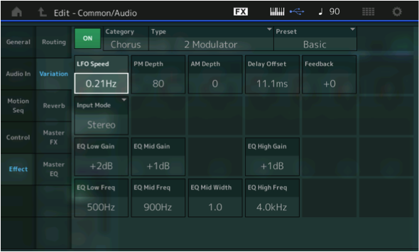
There are two SYSTEM EFFECT processors. One is called “Reverb” and provides the overall acoustics of the virtual room for your instrument ensemble; and the other is called the “Variation,” which provides time delay and other effects types you might want to apply to several music parts. In this example, the Variation Effect is assigned to a Chorus type called “2 Modulator” (a dual chorus effect that was extremely popular back in the 1970s-80s). Any PART with the Variation (VAR SEND) amount turned up will be sent to this dual chorus effect and therefore the changes assigned here would be applied to all the Parts using the Variation Effect in common.
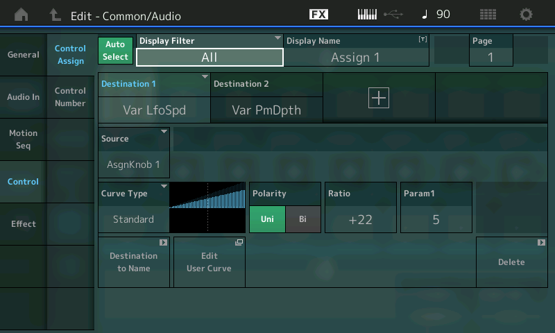
The Variation Effect parameters LFO Speed and PM Depth are assigned to Assignable Knobs 1 and 2, respectively. The assignments are done on the “Edit – Common/Audio” > Controller Assign screen. The very top line in the screen will always identify exactly where you are: “Edit – Common/Audio”. Let’s navigate there using the front panel buttons:
- Go to the main HOME screen by touching the “Home” icon in the extreme upper left corner of the screen or pressing the dedicated [PERFORMANCE (HOME)] button
- Whenever you are on the HOME screen, the PERFORMANCE NAME is highlighted – in this case, “Super Knob Common”
- Press [EDIT]
- Press the [COMMON] button (right side; the upper [COMMON] button). You’ll arrive at the “Edit – Common/Audio” edit screen

- In the screen select “Control” (the left column in the screen)
- In the second column select “Control Assign.” Make sure the AUTO SELECT option is active (green). This allows you to touch/turn/move a controller to immediately access its parameters in the screen
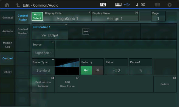
- Move ASSIGN KNOB 1 to immediately view its assignment (Vari LfoSpd) “Variation Low Frequency Oscillator Speed”
- Move ASSIGN KNOB 2 to view its assignment (Vari PmDpth) Variation Pitch Modulation Depth
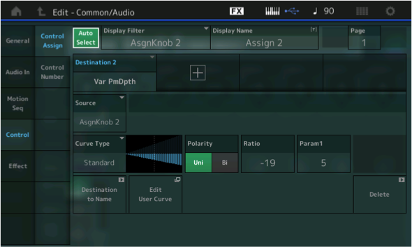
The Polarity setting in each is Uni (Unipolar). You can see that one has a Curve showing increase (a positive value) while the other has a Curve applying a decrease (a negative value). This means that the leftmost position of the Super Knob corresponds to the parameter value settings of the Effect window, which are:
- LFO Speed = 0.21Hz
- PM Depth = 80
Note that the parameter value is not 0; rather, it starts at the value as set, and is offset by the Super Knob.
To view the Variation Effect, touch “EFFECT” in the left column and “VARIATION” in the second column. As you can see, when the Super Knob is at minimum (fully counterclockwise), the LFO Speed is 0.21Hz and the PM Depth is 80
Listen while moving the Super Knob to the right. This increases the LFO Speed (Ratio is +22; the positive value indicates how steep the change is) and decreases the PM Depth (Ratio -19; the negative value indicates how steep the decline is). The LFO Speed starts at 0.21Hz and will increase from there. While the PM Depth starts at a setting of 80, the -19 (negative value) setting ensures it will be decreased from there. The Ratio determines what happens (direction and depth of application) to that parameter as the Super Knob is moved from minimum (0) toward maximum (127).
Because the Common Assign Knobs are routed automatically to the Super Knob, only the two assignments for Knob 1 + 2 are needed here.
Experiment with different values for both the Ratio values and the initial LFO Speed/PM Depth values to gain an understanding of what you are changing and how they interact.
Param 1 (Parameter 1) – experiment with this and observe how it changes the incline of the application of the control. It alters the shape of the Curve! So turning the Super Knob does not have to be a straight line increase or decrease (not at all); in fact, you can customize this “curve type” by an astounding degree. More “Parameters” will be added according the Curve Type selection – more on that in a future article. For now, let’s just stick to the Standard Curve.
Experiments
Important Hint: If LFO Speed is initially set to 0.0Hz, you will hear no modulation when the Super Knob is set to 0. By having an initial setting of 0.21Hz, there is a slight movement to the sound right away. This, of course, is a programming preference. Often you want a certain amount of movement to start, and then have the controller adjust that amount. Controlling the range of application is a programmer’s choice.
Try this: Highlight and adjust the LFO Speed parameter directly to hear its adjustment to the speed of modulation from a minimum of 0.0Hz to a maximum of 39.7Hz. You can do so by highlighting the parameter directly in the Variation Effect screen (shown above) and use the Data Dial to change the actual setting value. The initial setting of 0.21Hz is approximately one cycle every 5 seconds — as you approach 20 times a second, you will notice that the speed of modulation/movement itself is creating a low frequency pitch of its own; it practically becomes a buzzer, and at the maximum of 39.7Hz, the LFO is an audible oscillator. In other words, the LFO crosses over from being a low frequency “rate” into being an audible pitch.
Next, try applying higher frequency LFO Speedsat different PM Depth settings. Notice that if PM Depth is 0, naturally, you hear no modulation, no matter what the speed.
Here’s a theoretical situation where this programming would be used: You want to increase the LFO Speed but not have it go into the bizarre (pitch) range that happens as you approach maximum speed. So you want to increase the Speed but decrease the Depth, simultaneously. (This is a job for either two hands, or the Super Knob!)
This is just one of many different scenarios for assigning items to the Super Knob: One gesture accomplishes multiple things.
Summary: Here we have learned that COMMON Assign Knobs 1-8 are automatically assigned to be controlled by the Super Knob. The significance of this will become more clear when we begin to program the PART 1-8 Assign Knobs 1-8, where you can assign a PART parameter to an Assignable Knob and then link the Part’s Knob to the Super Knob.
Depending on your front panel EDIT selection (COMMON or PART 1-8), the Assign Knobs 1-8 take on different roles. If you envision a full front panel, where every Knob is a separate entity, you would have eight Assign Knobs for the COMMON edit parameters, eight Assign Knobs for PART 1 edit parameters, another eight Assign Knobs for PART 2 edit parameters, another eight Assign Knobs for PART 3 edit parameters, and so on. That would be a total of 72 physical Assignable Knobs in a Keyboard Controlled Performance.
Now the reason for the Super Knob comes into focus. You would probably never need to assign this many controls to a single playable sound – it would be difficult for your ear/brain to take in what was happening. But if you think of the eight Parts of a Keyboard Controlled Performance program as one big modular synth that has 64 Oscillators, 64 Filters, 64 Filter EGs, 64 Amplifiers, 64 Amplitude EGs, etc., you begin to understand the scale and scope of the controller matrix on tap here with MONTAGE. The word “massive” is not hype.
Each PART can have 16 assignable Destination (parameters) for the various controllers: Assignable Switches 1/2, Ribbon, Mod Wheel, PB Wheel, Foot Controllers, Aftertouch, and more. You can choose to use the Assignable Knobs directly or linked to the Super Knob. You can assign functions to multiple controller or spread them out as you desire. As we go deeper into the Motion Control Synthesis Engine we will explore these possibilities and pick up some tips on how to navigate and view exactly what’s going on. We highly recommend you take your time and unfold this a layer at a time.
In the example above, we see that the Super Knob can control multiple parameters simultaneously to achieve a specific result — in this case, the Chorus LFO speed is increased, at the same time its Depth is reduced. By adjusting the CURVE you can fine tune this dual action with a single controller gesture.
Extra Credit: Using the Navigation Shortcuts
Shortcuts:
- Call up the PERFORMANCE “Super Knob Common” and press the HOME icon
- Press [SHIFT] + [INFO] (HOME) buttons to jump to the Motion Control OVERVIEW screen
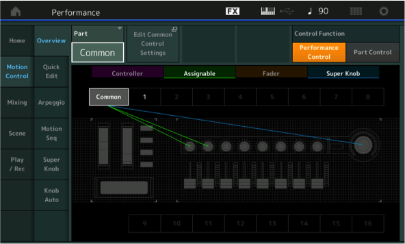
Here you can view the Controller Wheels/Ribbon, Assignable Knobs/Buttons, Fader and Super Knob assignments. Touch each of those words directly in the screen to toggle its connections on and off. Shown are the “Assignable” Knobs (green) and the “Super Knob” (blue). Turned off in the viewer are the “Controller” and “Fader.” You can see how the two knobs and the Super Knob are linked to COMMON.
Tip: In the “Part” box the word “COMMON” appears. Change this using the [INC/YES] button or the DATA DIAL. You can select any of the numbered Parts 1-16 (Assignable Knob parameters are available for PART 1-8). Notice how changing the value from “COMMON” to “PART 1”, “PART 2”, etc., actually changes the lighted front panel buttons on your right front panel. Selecting Parts — even selecting “COMMON” — can be done in the screen or by pressing an available corresponding button. Begin to make sense out of the lighted buttons — they always tell a story about what’s going on in your screen!
Return the item to “COMMON” on the OVERVIEW screen.
The box next to the PART > COMMON is a direct shortcut to the Controller Setting screen of the currently selected Part (“EDIT COMMON CONTROL SETTINGS”):
- Touch “Edit Common Control Settings” to go to the Common Edit Control screen
- This shortcut from the Controller Assignment takes you directly to the controlled parameter
“Aha!”
Power Tip: Once you arrive on the Controller Settings screen, you can view the 16 assigned Source/Destination functions of any Part, or the “Common/Audio” level, four at a time, by highlighting the DISPLAY FILTER box and selecting “ALL” (as shown in the screenshot below).
Use the PAGE function to view up to 16 Destinations per programming level. MONTAGE will keep track of the number of assignments per Part and for the Common/Audio level of editing. The “+” sign in a Destination box allows you to ADD a new Source/Destination parameter assignment. The “DELETE” box in the lower right corner removes the selected Source /Destination assignment.
If [AUTO SELECT] is green, you can move a controller to see what is assigned to it or you can move the cursor to the DISPLAY FILTER box and use the Data Dial to view the available options:
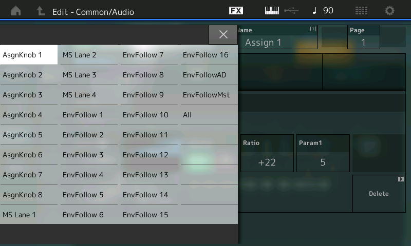
This Display Filter allows you to view (not alter) assignments made to a specific controller; when you change the Display Filter you are changing what you are viewing. It is a Display *Filter* because it is allowing you to see just what is assigned to the various Control Source options:
- Assign Knobs 1-8.
- Motion Sequence Lanes 1-4.
- Envelope Follower Parts 1-16, AD, and Master.
In this first programming example, we saw that the Super Knob is linked to COMMON and that COMMON is assigned to vary two Destination parameters. The Destination 1 box is assigned to control the Var LfoSpd. The box with a “+” sign will allow you to ADD a control routing (called a Destination). The “DELETE” box in the lower right corner will allow you to undo a Destination. There can be 16 Destinations (assignments) per PART.
Destination 2 in our example assigns Assignable Knob 2 to Var PmDpth. At this upper COMMON/Audio level of the architecture this includes the following PARAMETER DESTINATION:
- INSERT B (when assigned to the A/D INPUT)
The significance here is that you can control, in real time, the Insertion Effects that are assigned to the A/D INPUT Part. Each MONTAGE PART (including the A/D Input) has its own dedicated dual Insertion Effect processor – which can be automated by the Motion Control Synthesis Engine. A Microphone can use a pair of Insert Effects (a Delay LCR and something else) and you can, for example, control the Dry/Wet Balance and number of repeats (Feedback level) by assigning control to one or more of the available COMMON Assignable Knobs:
- INSERT A (when assigned to the A/D INPUT)
- REVERB (System Effect)
- A/D INPUT Parameters
The significance here is that, at the top COMMON level, all eight Parts can be influenced (or not), depending on how much signal you send into the shared System Effect processors. In other words, every PART has a SEND amount into the Reverb and Variation processors, and you can determine how much per Part. Effect parameters for the chosen Effect TYPE will be available as assignable Destinations. We saw this in the first example, where we were controlling parameters within the 2 Modulator Chorus TYPE:
- A/D INPUT Parameters
Here you can control the VOLUME, as well as the SEND amounts to the Reverb and Variation SYSTEM EFFECTS for the A/D INPUT Part. This gives you full automation of audio signal coming into MONTAGE — which could be anything you place in front of a microphone, or another keyboard, or other playback source:
- MASTER EFFECT
The significance here is that you can automate control over the Master Effects – making it a PART of the Motion Control situation:
- PART 1 – AS1 through AS8
- PART 2 – AS1 through AS8
- PART 3 – AS1 through AS8
- PART 4 – AS1 through AS8
- PART 5 – AS1 through AS8
- PART 6 – AS1 through AS8
- PART 7 – AS1 through AS8
- PART 8 – AS1 through AS8
-
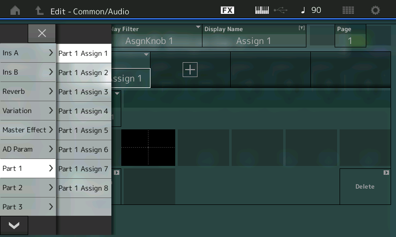
It is very important to understand these assignments. They allow the Super Knob to control specific items within each separate PART. As we stated at the beginning of this tutorial, the Super Knob automatically controls the eight COMMON Assignable Knobs 1-8 and it works directly on those upper level/shared parameters. Notice that listed here is each of the eight Keyboard Controlled PARTS, as well as each of their eight Knobs. This means that, with an assignment selection here, you are linking the individual PART’s control of a Destination parameter to the movement of the Super Knob.
In our next lesson, we will see how this intermediate step opens the door to a wide, wide world of synth patching. We will drop down a level to the individual Part and the parameters that only affect a single Part within a Performance. We will assign PART 1’s Assignable Knob 1 so that it follows the movement of Super Knob and yet controls a parameter exclusively (locally) within just one Part, PART 1. The selection of potential Destinations will change and will include parameters specific to this particular PART as an individual component within the PERFORMANCE.
Catch up on the previous article in the series: “Mastering MONTAGE 1: The Super Knob” here.
Next Article: “Mastering MONTAGE 3: Super Knob Unipolar” is available here.
Keep reading