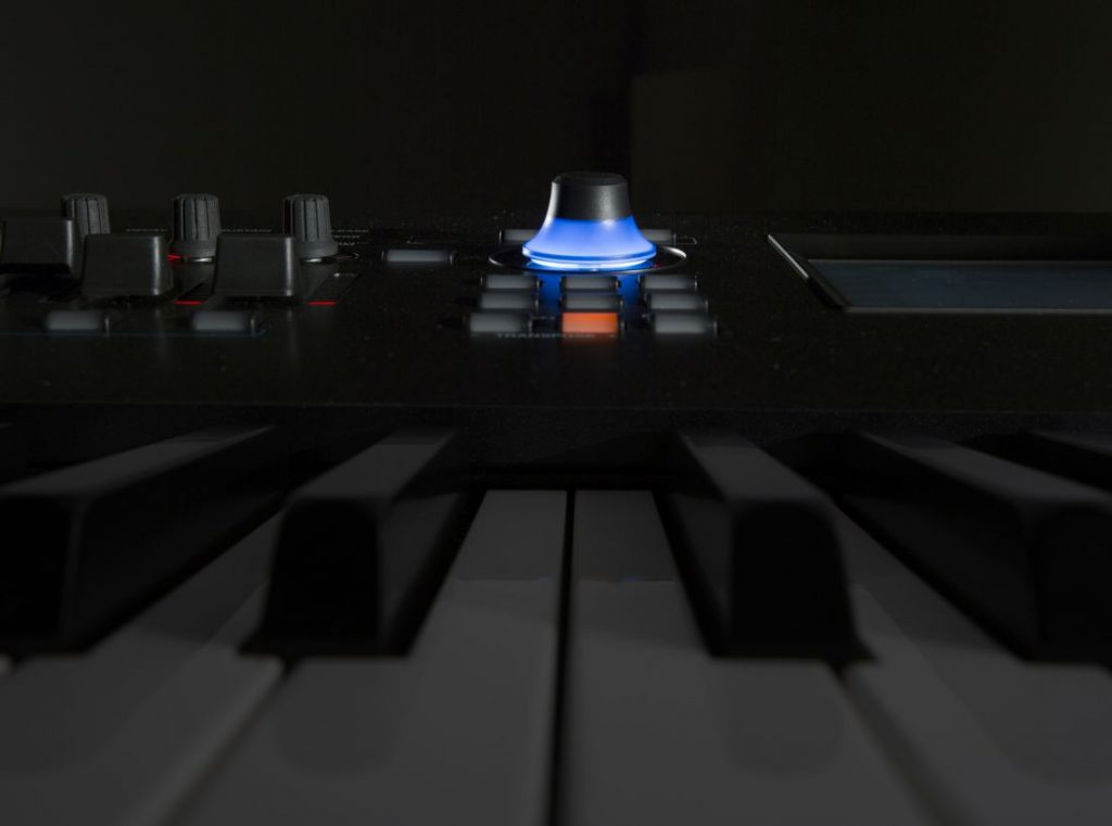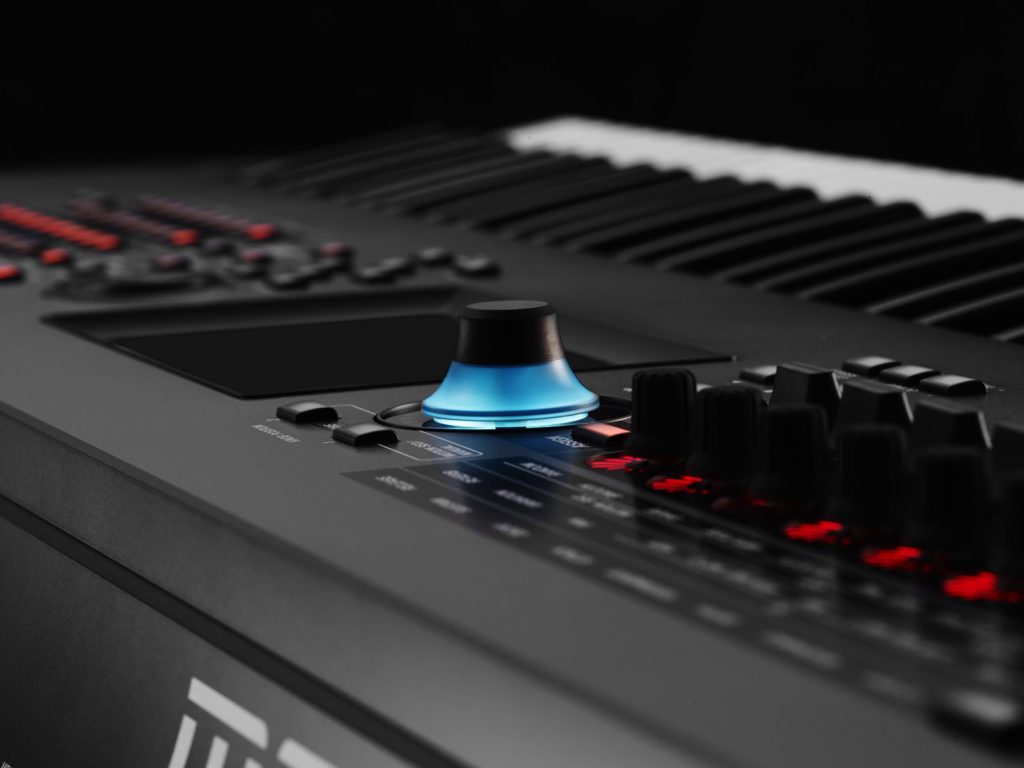
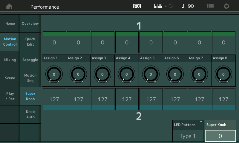
MONTAGE Super Knob Unipolar
Ready to jump into the next lesson about MONTAGE and the Super Knob?
The next two PERFORMANCE examples show the assignment of a Part’s parameters to the Super Knob, which are a bit more complex than using Common parameters.
(NOTE: The Live Set used in these tutorials can be downloaded here.)
Example 3: Super Knob Unipolar+
The first step is assigning the used Part Assignable Knob 1 to the Common Assignable Knob 1, which must be done on the Common > Control Assign screen. Instead of assigning directly to a parameter, we are assigning control of PART 1’s Assignable Knob to COMMON (Super Knob) control. Remember, the Super Knob automatically controls all eight Common Assignable Knobs – and the Part Assign Knob 1 can be used to control parameters within this specific Part.
This means that whatever we assign to PART 1’s Assignable Knob will automatically be controlled by the Super Knob. Begin by loading in “PERFORMANCE 2: Super Knob Unipolar +”:
Once again, we will navigate to the upper level of editing (Common/Audio) and assign Part 1’s first Knob to the COMMON Assign 1.
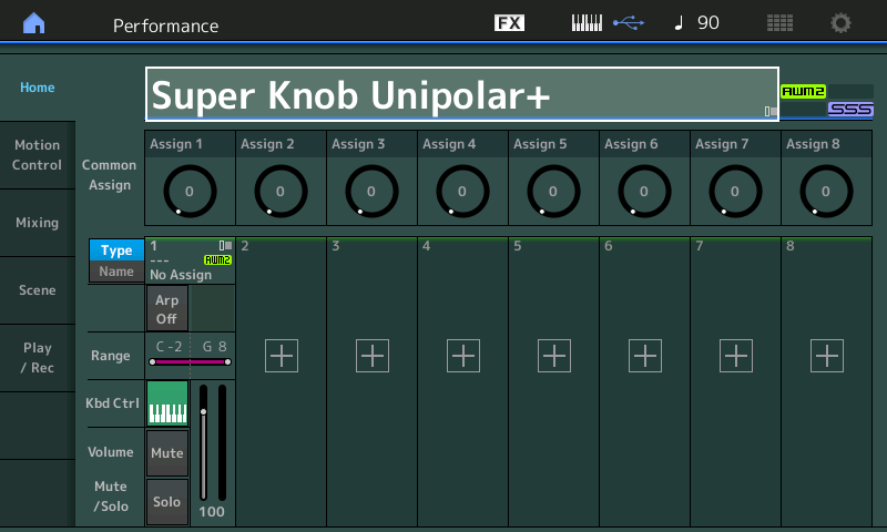
- Go to the HOME screen (press the “Home” icon in the upper left corner of the screen). This highlights the PERFORMANCE NAME: “Super Knob Unipolar+”.
- Press [EDIT]
- Press the [COMMON] button (right side upper COMMON button).
- In the screen select “Control” (left column of the screen) > “Control Assign” (second column).
- Make sure the AUTO SELECT option is active.
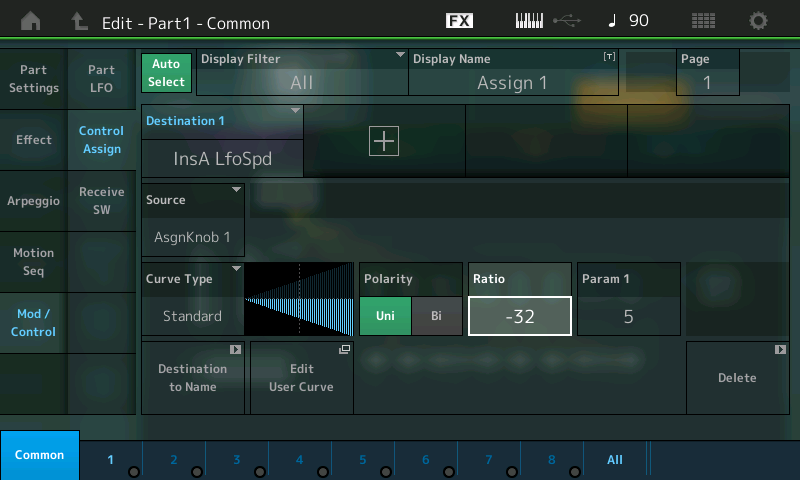
- Move Assignable Knob #1 to recall its setting (“Destination 1 = Part 1 Assign 1”):
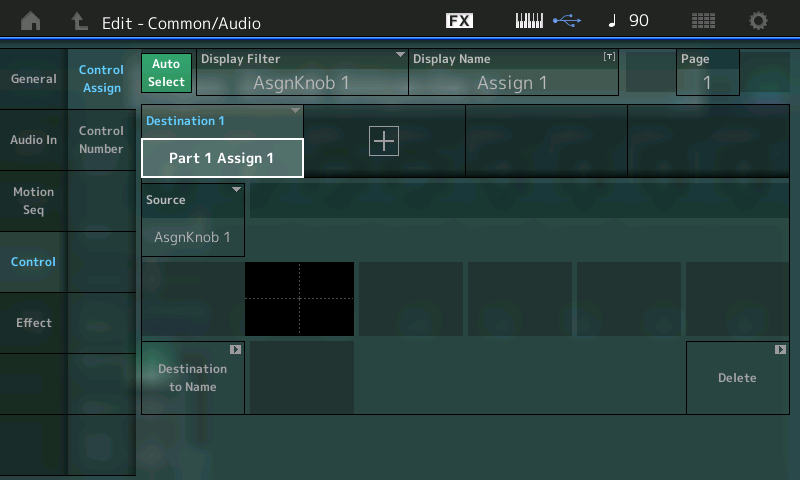
The first COMMON assignable destination (Destination 1) for this Performance concerns the program occupying PART 1. This assignment gives the Super Knob control over Part 1’s Assignable Knob 1. To see exactly what “PART 1 Assign 1” is controlling, we must edit the Program occupying PART 1. Remember, you can think about the playable Performance as having 72 Assignable Knobs, where Common has eight Knobs, and each of the eight possible Parts can have eight Assignable Knobs. We are assigning the Super Knob to control a parameter within PART 1 – we do so by linking Part 1’s Assign Knob #1 here.
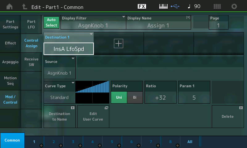
In this Example Performance, we are assigning the first of the eight (Common) Assignable Knobs to PART 1 of this PERFORMANCE. To manually navigate to the actual parameter that is being controlled, go to the EDIT – PART 1 – Common screen. Here’s how:
- Press the [PART SELECT 1/1] top right front panel and select PART 1. This should light the lower [COMMON] button for ELEMENT/OPERATOR. (If it does not light, it’s an indication that you were last viewing an individual ELEMENT within this program; in that case, simply press the lower [COMMON] button.) For convenience, there’s also a “Common” button found in the lower left corner of the screen (blue) along with access to Elements 1-8, or a view that will let you see all eight together:
Hint: To understand this second Common button, remember that the playable PERFORMANCE can have eight KBD CTRL PARTS – and that together they share the PERFORMANCE NAME, the SYSTEM EFFECTS, the MASTER EFFECTS, the MASTER EQ, and that they include the AUDIO IN settings. Each PART is a like a complete Motif XF level VOICE with eight Elements – each with its own Part COMMON parameters. Each Part has its own Name, its own Insertion Effects, and its own eight Assignable Knobs! So if you think of each PART as a separate synthesizer with its own complete set of parameters, what we are doing is linking control of this synthesizer with a, well, you know, a “SUPER” knob – a single knob that, when moved, can send a message that is divided out among the rest of the separate synthesizers. Don’t worry if it takes a minute or two for this to sink in – it’s as if we are dealing with a large modular synth, where a Keyboard Controlled program (with eight complete synthesizers) is linked to this MOTION CONTROL ENGINE. Like patching cables in an old-school analog synth, we are linking control. Later we’ll see how we can limit the range of controllers too.
For former Motif/MOXF users, this is very much like being in a Song/Pattern Mixing setup, then dropping into VCE EDIT when creating a Mix Voice. However, in MONTAGE, every edit has room to be stored and you are editing the Part directly. This second level of Common parameters are Part Common parameters.
- Select “MOD/CONTROL” (left column of the screen) > “Control Assign”. The Controller setting is Unipolar with Ratio +32 (giving a linear response, as shown in the screenshot above).
- With AUTO SELECT highlighted, you can turn Assignable Knob 1 and view the assigned Destination = InsA LfoSpd. This happens to be the LFO Speed of the CLASSIC FLANGER assigned to PART 1.
- Press [EFFECT] (second item left side of the screen to view the Effect) > and select “Routing” for PART 1.
- INSERT A is the Classic Flanger:
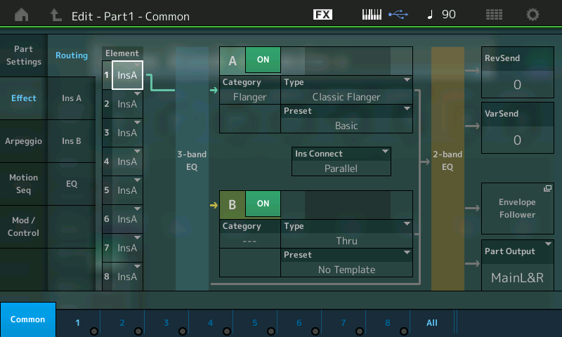
You can edit the Effect parameters by touching “INS A” in the second column.
Note that the LFO Speed of the Classic Flanger is set to 0.00Hz (minimum) in the Part Effect window:
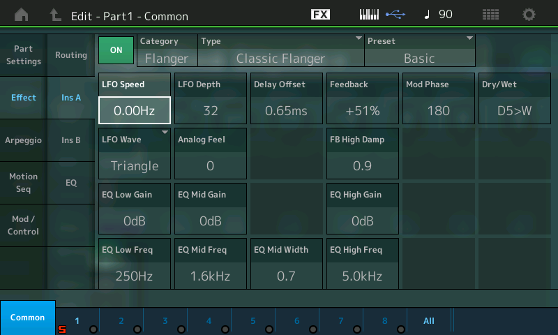
The Super Knob position 0 (left) is the start position. It corresponds to the parameter setting of LFO Speed = 0.00Hz.
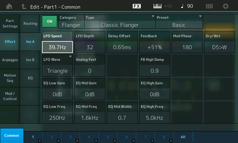
The Super Knob moved from left to right controls the complete parameter range from LFO Speed 0.00Hz to 39.7Hz.
(Note: The values do not animate in the MONTAGE screen when you move the Super Knob although you can clearly hear the Speed change as it is moved.)
The potential here is tremendous: One knob can be assigned to do multiple things with different ranges for different areas of the Performance.
Summary: At the upper COMMON (overall level) we have assigned Super Knob control over PART 1’s Assign 1 Knob. This is done by linking the “PART 1 ASSIGN 1” (PART 1’s Assignable Knob 1) part to the Super Knob so that whatever parameter is selected for this knob to control will be influenced by the Super Knob. The “DESTINATION 1” within PART 1 indicates that this is the first controller assignment for PART 1. There are a maximum of 16 Destinations per PART. In this example, the LFO SPEED of the Classic Flanger is the selected parameter within PART 1.
Again, we are limiting ourselves to a single Part Performance in this case. Each additional PART added under Keyboard Control will have the same opportunities to be programmed with their own set of eight Assignable Knobs and destination parameters. The assignment we make for Part 1 will only apply to Part 1; the Classic Flanger is an Insertion Effect and belongs only to this Part, Part 1.
Example 3: Super Knob Unipolar-
This example shows the modulation of the LFO Speed in the opposite direction (negative). This is achieved here by starting the Classic Flanger at its highest Speed (39.7Hz) and setting the Polarity to a NEGATIVE value, so that applying the same movement reduces the LFO SPEED from maximum to minimum.
The Classic Flanger LFO Speed in the Part Effect window is set to 39.7Hz (maximum):
The Part Controller setting is Unipolar with Ratio = -32.
- Select “Mod/Control” > “Control Assign”:
The Super Knob position 0 (left) is the start position. It corresponds to the parameter setting of LFO Speed at maximum = 39.7H:
The Super Knob moved from left to right controls the complete parameter range in reversed order from LFO Speed 39.7Hz to 0.00Hz.
Extra Credit Exploration:
In this example, the COMMON ASSIGN KNOB 1 has been tasked with controlling PART 1’s Assign Knob 1. PART 1’s ASSIGN KNOB 1 is set to control the Part 1 INSERTION EFFECT “A” parameter (LFO SPEED).
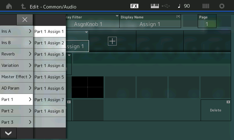
Touch the parameter contained within the “DESTINATION 1” box to reveal the list of potential assignment destinations that can be selected. There are a ton of potential options – more than you might think. Use the DATA DIAL to explore the options. In this particular example, by selecting PART 1 > PART 1 Assign 1 we are linking PART 1’s first knob with the Super Knob.
These potential Destinations – the parameters available via the upper overall “COMMON/Audio” level of the program – will give you an idea of the depth of the engine. When you see the top line indicate “EDIT – Common/Audio“ you can assign these parameters to the Super Knob. The INSERT A and B referred to here are those dedicated to the A/D (Audio) INPUT PART. Like every other PART, it has its own Dual Insertion Effect. The A/D INPUT is grouped with the COMMON overall parameters. This is why this level of the architecture is referred to as “Common/Audio”:

If you select an Ins A or B(A/D Part), the Reverb, the Variation, or the Master Effect can each have as many as 24 potential parameter destinations (the actual number of available parameters will vary depending on the effect TYPE currently active in the processor). When an Effect Type is assigned to the processor, the parameter names that are available to be controlled will automatically appear in the list. Those parameters not available for real time control will not appear. (Only parameters that are deemed musically useful are available for real time control.)
If you select the “AD Param” you can control Volume, Rev Send and Variation Send amounts of an incoming signal. These are followed by each of the 16 MONTAGE synth PARTS, each of which have eight assignable knob destinations. That’s 128 Assignable Knobs, plus the eight for the Common/Audio level.
As we’ll learn, Parts 1-8 can be linked with the Super Knob, but every Part has its own eight Assignable Knobs for when that Part is individually selected (highlighted).
Press the “X” in the screen to exit or press [ENTER] to make a selection assignment.
If you touch the “DISPLAY FILTER” box, you can see all of the assignable devices. Changing the Display Filter does not change anything other than what you are currently viewing.
Overview shortcut:
Again, let’s practice navigating using the available shortcuts.
- Recall the PERFORMANCE and touch the HOME icon.
- [SHIFT] + [INFO] = Overview screen (shown below). Notice that in the PART box, “PART 1” is selected and in the diagram a highlight box also appears around the number “1”:
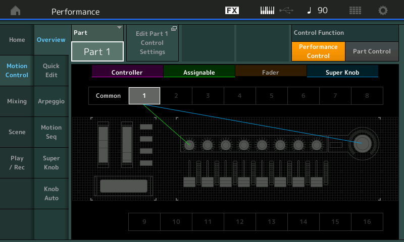
The Part Assign Knob 1 is linked to PART 1 (green line), which is under control of the Super Knob (blue line). You can go from this information screen directly to “Edit Part 1 Control Settings”. This shortcut will take you directly to the Part Mod/Control > Control Assign screen. If you then activate the AUTO SELECT box, touching/moving a controller will display its assignment. Or simply set the “Display Filter” = ALL to view all assignments for the currently selected PART.
Important Note: Parameter Destinations for the COMMON/Audio level of the PERFORMANCE are different from the available parameter Destinations for an individual synth PART. The INSERT EFFECT A and B that appear among the COMMON/Audio Destinations refer to the A/D INPUT (AUDIO IN) PART, while the INSERT A and B that appear among the synth PART parameter Destinations are those applied to this particular PART.
Catch up on the previous article in the series – “Mastering MONTAGE 2: Super Knob Common” here.
Next article: “Mastering MONTAGE 4: Super Knob Bipolar” is available here.
Keep reading