Using the MONTAGE Assignable Knobs
Here’s a lesson in how to leverage the power of MONTAGE using the Part Assignable Knobs.
(NOTE: The Live Set used in these tutorials can be downloaded here.)
PERFORMANCE 9: Assignable Knobs
The previous examples in this series showed how to use the Assignable Knobs of the Performance Parts for building Super Knob assignments. However, independent of the Super Knob, you can use the Part Assignable Knobs for individual assignments after selecting the Part.
Important: You can control only one Part at the same time with Assignable Knobs (the currently selected/highlighted PART). But you can use the Super Knob and the Assignable Knobs of the selected Part at same time!
This example shows how Super Knob assignments can be combined with individual assignments to the Part Assignable Knobs (which are not routed to the Super Knob). Getting your head around this may take some time, but before there was a MONTAGE with a Super Knob, an Assignable Knob would be assigned to control a specific parameter within the current PART. This can still be done, and it remains unaffected by the movement of the Super Knob for this PART. Often a PART of your PERFORMANCE may be selected (highlighted) for individual direct play/control, while the others are responding to messages generated by the Arpeggiator. For example, you might have a two-Part split Performance with a lead sound in the right hand and a bass in the left, and you might want to have a knob that just affects the lead Part. In such a case you may opt to simply use an Assignable Knob independent of the Super Knob.
Each PART, when selected for direct play/control, has access to the three rows of eight Knob functions plus its own eight Assignable Knobs. In effect, you have 32 Knobs, plus the physical controllers (MW, PB Wheel, the two Assignable Switches, Ribbon, Aftertouch, FC1/FC2, Faders [Control Sliders]), the Motion Sequences, Arpeggios, the Envelope Follower, etc. – all of which can be called upon while the Part is selected. An extensive Receive Switch matrix allows you to determine which physical controllers are active per Part. Between the Super Knob – which can work independently – and the controls available to your currently highlighted (selected) Part, you can design almost any scenario.
This example Performance includes only one Part with a typical fat sawtooth synth pad. All eight Part Assignable Knobs are assigned to parameters within this PART, but only two of them (1 + 2) are also routed/linked to the Super Knob:
In the previous examples of the SUPER KNOB assignment, we saw how, on the Performance upper “COMMON/Audio” level, you needed to assign “Part 1 Assign 1”, “Part 1 Assign 2” and so on, to make each Knob accessible via the Super Knob. In this example, only these first two are using the Super Knob. The other six Knobs are individually accessible when you highlight/select the PART, as we’ll see below. (This is very similar to the Motif XS/XF Performance, where, when you selected an individual PART, the Assign 1 and 2 Control Knobs would address parameters for just that individual PART).
- To view the Assignable Knob layout, go to the OVERVIEW screen – [SHIFT] + [PERFORMANCE (HOME)] – or from the main screen touch “MOTION CONTROL” > “OVERVIEW”
- First, view the Performance COMMON Assignable Knob assignment:
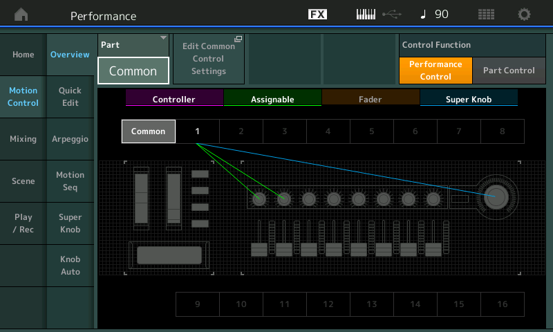
- Change the PART parameter from “COMMON” to “PART 1” to view the Assignable Knob layout for PART 1:
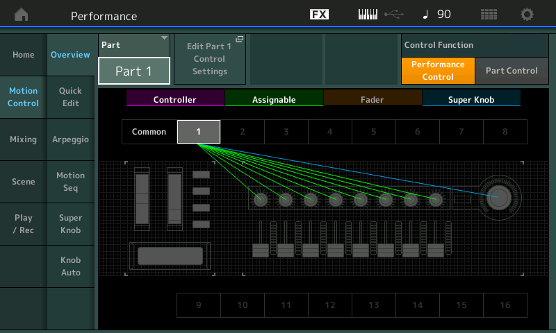
There is one DESTINATION parameter assignment for each of the PART’s eight Assignable Knobs.
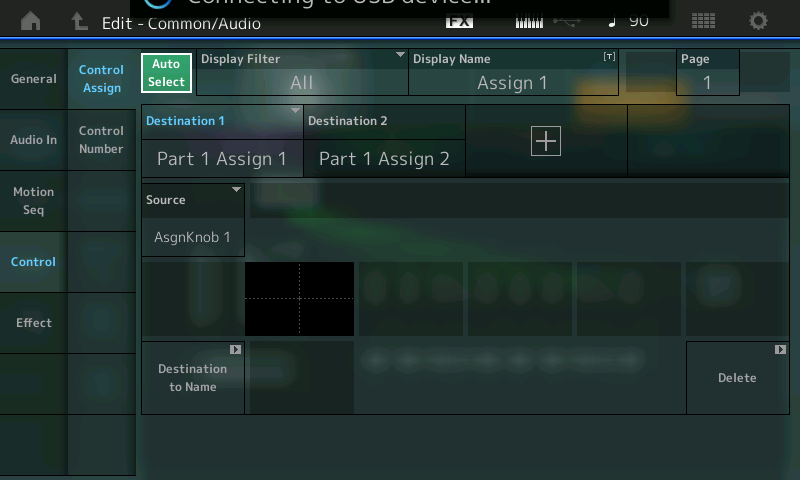
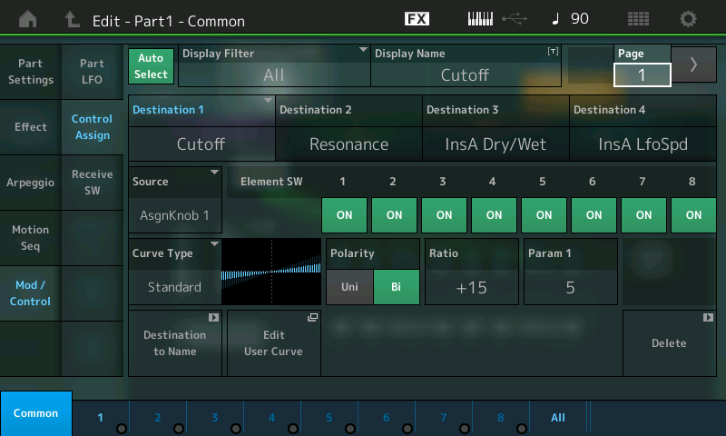
To view the actual 8 Destination Control Settings, use the “Edit Part 1 Control Settings” shortcut – set the DISPLAY FILTER to “ALL”.
You can view Destination 1 ~ Destination 4 on the first Page. There are two PAGES.
PAGE 1:
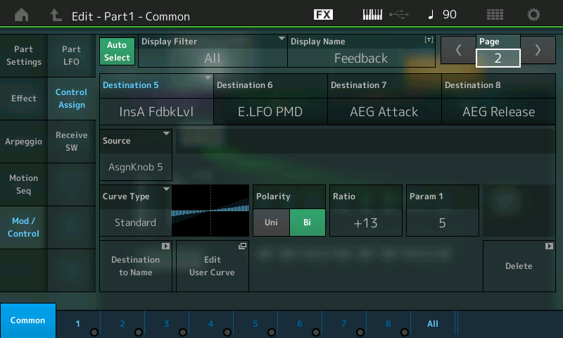
PAGE 2:
The currently displayed “DESTINATION” has a number from 1-16. Touch that designation to view its data. Touch the parameter setting to view an overlay of possible parameter Destinations.
The Super Knob starts with the center position (64). This is useful for combining it with Part Assignable Knobs, which are set to center position by default. For this reason, selecting Bipolar (Polarity) for all assignments in the Part Controller Box is needed, since Bipolar allows you to move the parameter up or down, depending on whether a positive or negative value is set for RATIO. Positive values increase as the Knob is turned clockwise
The Assignable Knobs can be used for controlling the listed eight parameters: Cutoff, Resonance, Insert “A” Dry/Wet, Insert “A” LFO Speed, Insert “A” Feedback Level, Element LFO Pitch Modulation Depth (vibrato), AEG Attack, AEG Release.
At same time you can use the Super Knob, which controls the Assignable Knobs 1+2. But you should avoid using the Super Knob and the Assignable Knobs 1+2 at same time, because they are controlling the same parameter.
You can see the movements of the Super Knob at the LEDs of the Assignable Knob 1+2.
I’ve edited and stored this PERFORMANCE, renaming the individual Destinations for this PART (PART 1) (DISPLAY NAME). By default, they are simply named: Assign 1, Assign 2, Assign 3, Assign 4 and so on.
This DISPLAY NAME will appear on the main PERFORMANCE screen when PART 1 is the “selected” (highlighted) PART, as shown below:
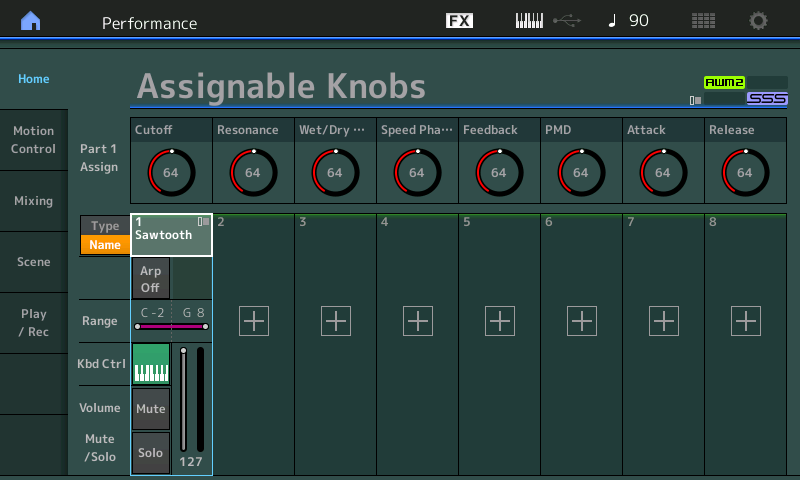
They will read ASSIGN1, ASSIGN2, etc., when you are on the upper level of the PERFORMANCE (because they can be doing different things if you activate other PARTs), but if you select Part 1, the name you provide as the “Display Name” will appear. (Select the Part by pressing [PART SELECT 1/1] or by touching the TYPE/NAME box above PART1.) Now you will see that I’ve identified what each of them is doing to PART 1. Because you can SELECT only one PART at a time, it makes total sense to be able to read what that Knob is assigned to – this cuts down immensely on the guessing about what a Knob is doing!
It appears that many of the PRESETs simply have the word “Assigned” as the PART “Display Name” – which at least lets you know it is doing something. If it is not assigned, the Display name area appears blank.
Using the “Display Name”
From the upper COMMON/Audio level (or when the PERFORMANCE NAME is highlighted), the KNOBS will simply read ASSIGN 1 – ASSIGN 8. When you select an individual PART (either by touching the PART Name or by pressing [PART SELECT 1/1] ~ [PART SELECT 8/8]), you have the option of viewing the KNOB assignment by what it is doing. You can even give it a “nickname” – anything that you wish. This is extremely cool because you can be descriptive. The Presets only indicate which Knob is “Assigned” when you select an individual PART.
Imagine the PART Knob is controlling an FM Element that causes RING MODULATION when you raise its Modulation Index (Output Level). Saying it is “Output Level” is not as helpful as naming it “+RingMod”.
So selecting any single PART 2-8 (so that it is the highlighted PART) will show you what each of the knobs is assigned to control. This can be very useful and can make exploring Performances much easier because, when scuba diving, it can get quite deep!
Catch up on the previous article in the series – “Mastering MONTAGE 7: Super Knobs Values” here.
Next article – “Mastering MONTAGE 9: Controller Box Switches” – available here.
Keep reading