The MONTAGE Controller Box Switches
In this lesson, we’ll learn how to use the MONTAGE Controller Box Switches.
(NOTE: The Live Set used in these tutorials can be downloaded here.)
PERFORMANCE 10: ControllerBoxSwitchA
Sometimes you need to make control assignments only to specific Elements within the AWM2 PART (or to specific Operators within the FM-X PART). In the default setting, the control assignments are valid for all Elements of a Performance. The individual assignments for Elements can be done on the Controller Set screen – you can select the Element for Destinations that allow individual selection.
This means that all used control settings made in the Part Controller Set are initially enabled. If you select a parameter that allows for individual Element assignment, you must OPT OUT for the individual Element. The default is that an ELEMENT is set to OPT IN. In other words, if you select a parameter Destination that does offer individual ELEMENT assignment, the Elements are initially set to active (ON) by default. If you don’t want to control an Element, turn its individual Switch OFF. Of course, if you do not select the parameter Destination, its being ON or OFF is of no consequence, because you will not be changing anything.
For better understanding, it may help to compare this function with the corresponding function in the Motif XF – the “Element Switch” in the Controller Set Assignment:
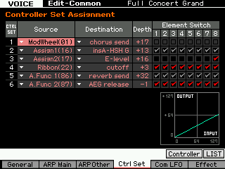
As you can see in the above screenshot, the Effect parameters are unchecked or greyed out because they cannot be used individually for Elements. This is because of the selected Destination. The entire sound (all Elements together) is routed through the selected destination (Effect). “InsA-HSH G” (Insert A – High frequency Shelving Gain), which is an EQ, and “Reverb send” are both situations where the entire program is processed and so it is not possible to select just a single Element.
In CONTROLLER SET 4 and 6 (Destinations “cutoff” and “AEG release”, respectively) the boxes are checked for all Elements. Here you have a choice, and all Elements are opting in.
In CONTROLLER SET 3 (Destination “Element Level”), the box is checked only for Element 8. The programmer would have had to uncheck Elements 1-7 in order to OPT OUT.
A CONTROL SET on the Motif XF consisted of a SOURCE (physical control) and a DESTINATION (target parameter). DEPTH dealt with the application of the controller – both range and direction – to appropriate Destinations, but only when you were provided the option to select specific Elements individually. Also, the Motif XF had only six Control Sets, while MONTAGE provides 16 Control Sets per PART, plus an additional 16 for the COMMON/Audio level of editing. There are also a host of new parameters like Curve Type and Polarity, as well as advanced shaping tools that let you customize the application of controllers.
These new shaping tools exponentially increase the DEPTH function that was available in the Motif and MOXF series because it no longer has to be linearly applied. In fact, MONTAGE allows you to completely customize the DEPTH shape, plus you can apply it manually or automate its application. This is at the core of the MONTAGE Motion Control Synthesis Engine.
The layout is a bit different, but the operation is fundamentally the same:
- If a Performance Part doesn’t require individual Element assignments, you can keep the Controller Box Switch as it is – all Element Switches default to ON.
- If you want to make individual Element assignments, you have to edit the Controller Box Switch matrix.
CONTROL ASSIGNMENTS are easy to deal with because they are seen within the PART’s Element/Operator view and are made intuitively as you think about them. It’s very much like patching a modular synth in that, as you build your sound, you make the necessary connections/assignments. The key thing here is that the Destination (parameter) determines whether or not the Element/Operator Switches appear or not. Obviously, some Destination parameters are PART destinations (i.e., they affect all Elements or Operators together, like common Volume, Send to Reverb and Variation, etc.) while others are individually switched per Element or Operator (like Element Level, Element Pan, AEG, FEG and PEG parameters, Cutoff, Resonance, LFO, etc.). This can be seen as equivalent to the kind of “patching” you would do in voltage controlled analog synthesizers if you had a wall unit full of modules. Think about all the individual envelopes you can control within the eight PARTS – each with as many as eight Elements (if AWM2) or eight Operators (if FM-X).
The “PERFORMANCE 10: ControllerBoxSwitchA” example includes a simple Super Knob morphing between two different organ Waveforms within a single Part:
Element 1 = Gospel.
Element 2 = 1st Four Draw.
Instead of the organ sound occupying a Part, here each organ sound is a single Element within the same Part.
Element 1 Gospel is assigned to the right (fully clockwise) position of the Super Knob. Element 2 1st Four Draw is set to the left position. In the center position you will hear an equal mix of both.
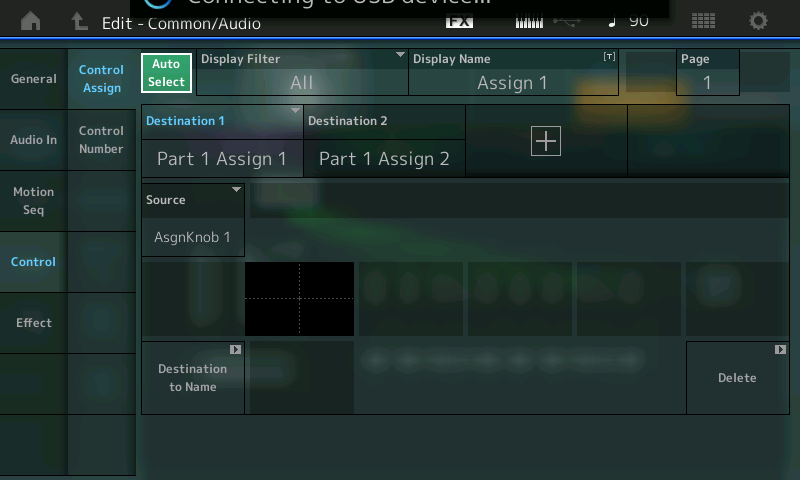
The first step is to make the Super Knob assignments in the “Common/Audio” Controller Box: The first two Knobs (Assign1 and Assign2) are set to link with PART 1 on this upper Common/Audio level (the Super Knob level). Instead of morphing between PARTS, we are now working within a single PART by manipulating individual Elements (since this is an AWM2 sample based program). Each Element references a Waveform. A Waveform organizes a set of samples mapped to respond across the keyboard at specific pitches and velocities.
From the HOME screen:
- Press [EDIT].
- Press the upper [COMMON] button.
- Select “Control” > ” Control Assign.
- With the AUTO SELECT (green) active you can view the assignments either by moving the Knob itself or setting the DISPLAY FILTER = ALL:
Next, follow the assignments in the Part Controller Box, which is basically the same as morphing between Parts, but this time using the Element Level as destination. Let’s take a look at the two PART 1 destinations:
- Press the [PART SELECT 1/1] to view “Edit – Part1 – Common”.
- Select “MOD/CONTROL” > “CONTROL ASSIGN”.
- Ensure that “Auto Select” is active (green).
- Move ASSIGN KNOB 1:
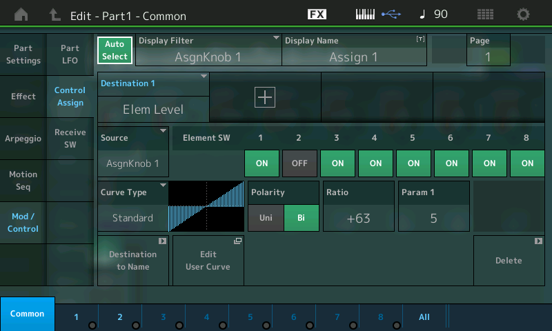
- Then move ASSIGN KNOB 2:
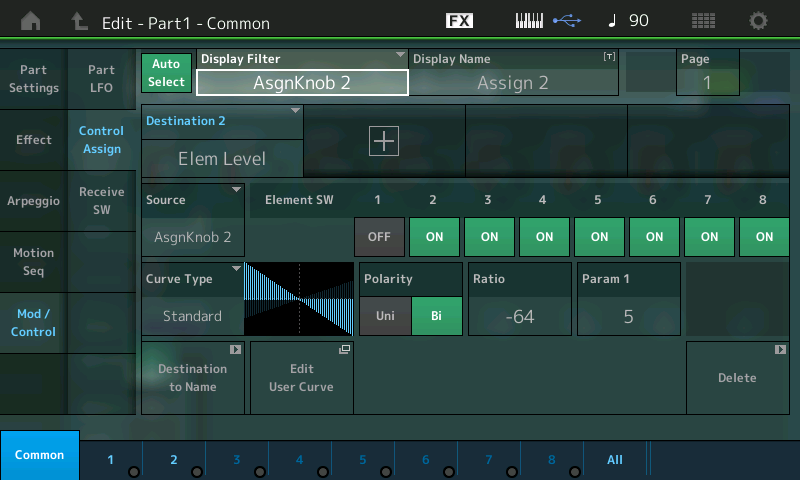
(Top screenshot) Assignable Knob 1 (Ratio +63) = Element Switch 1 ON, Element Switch 2 OFF.
(Bottom screenshot) Assignable Knob 2 (Ratio -64) = Element Switch 2 ON, Element Switch 1 OFF.
It should be noted here that you can STORE the position of the Super Knob with the PERFORMANCE. So if you want this Performance to come up with the 1st Four Draw Element alone, you would store the Super Knob at a value of 0. If you wanted the Gospel Element alone, you would store the Super Knob at a value of 127. If you wanted to recall the sound with both Elements, you would store the Super Knob at 64 (for both at equal level), or any balance you desire.
From the PERFORMANCE (HOME) screen:
- Touch “Motion Control” in the main screen’s left column.
- Touch “Super Knob” in the second column.
- SUPER KNOB value is in the lower right corner.
SOURCE: DESTINATION CONTROL ASSIGN Shortcut:
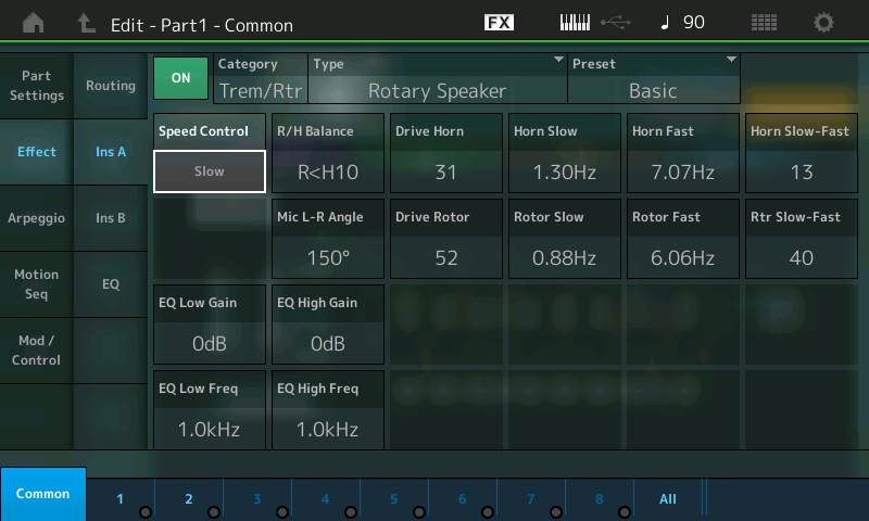
This is a good example of how easy it is to assign a parameter (Destination) to a controller (Source) with MONTAGE. Up until now on our “scuba tour,” we’ve been going through all the screens where this all takes place, but here’s a quick and easy assignment for you snorkelers. Say you’ve selected the Rotary Speaker TYPE as Insert Effect “A” and you want to assign Rotary Speaker: Speed Control to the MOD WHEEL. (Notice this Performance does not have it assigned).
Start from the HOME screen (touch the icon in the upper left corner):
- Press [EDIT].
- Press [PART SELECT 1/1] to view the PART 1 parameters.
- Touch “COMMON” (blue) in the lower left corner or the screen.
- Touch “EFFECT” in the left column.
- Touch “INS A” to view the parameters of the Rotary Speaker.
- Move the cursor to highlight Speed Control (shown):
- Press the [CONTROL ASSIGN] button (located to the left of the screen below the Super Knob), which is now illuminated. The Destination Parameter will appear in the screen and it will tell you to activate (move) the controller you wish to assign:
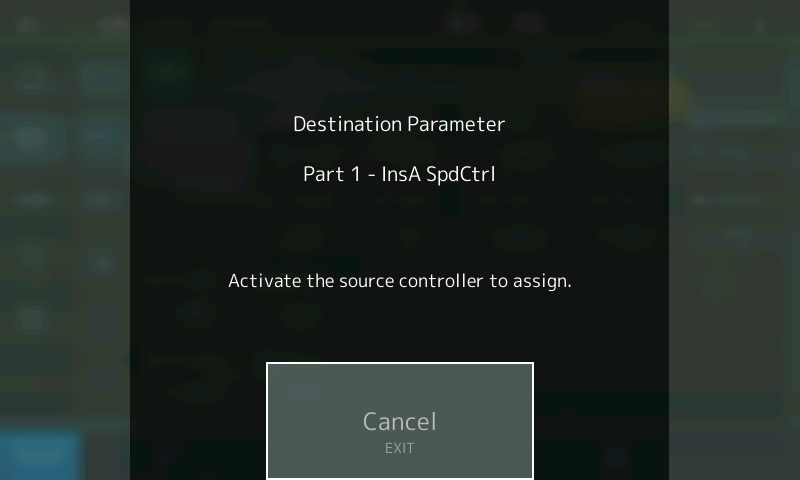
- Now move the Mod Wheel:
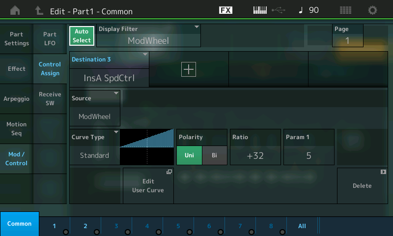
Done! This procedure takes you immediately to the Controller Assign screen, where you can tweak the Controller response (Depth) and/or Delete the assignment (Lower right corner of this Control Set screen). Notice that the Element Switches do not appear since they are unavailable – that’s because all Elements will be affected by the application of the Rotary Speaker Speed change.
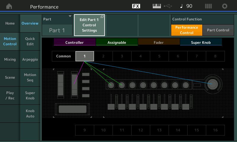
In the OVERVIEW you can now see how the MW (Controller) is linked to PART 1 (magenta):
The [CONTROL ASSIGN] button, located to the lower left of the screen below the Super Knob, will glow whenever you move the cursor highlight to a potential assignable parameter. This allows you to rapidly assign, then scale and shape the application of that controller.
Keep reading