MONTAGE Super Knob Complex
In this lesson, we continue our insight into the capabilities of the MONTAGE Super Knob, with an emphasis on EDM applications.
(NOTE: The Live Set used in these tutorials can be downloaded here.)
PERFORMANCE 7: Super Knob Complex
This type of Performance is very useful for typical EDM Synth Chord Sequences. The Super Knob modulation works from percussive sequence sound (left) to full chord sound (center) and continues with filter control from center to right.
Here we’ll learn how to divide the ranges of Super Knob movement into “left-to-center” and “center-to-right” for two different modulations. Compared to the previous examples, this Super Knob programming is considerably more complex and multi-dimensional.
This will require routing the corresponding Part Assignable Knobs to the Common Assignable Knobs on the “Edit-Common/Audio” level and then assigning the PART Knobs to the controlled Part destination parameters.
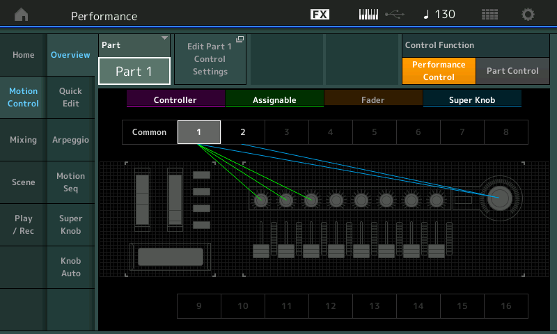
Let’s decipher what Knobs are assigned to the Super Knob. By looking at the OVERVIEW screen we can learn that PART 1: AssignKnob1, AssignKnob2 and AssignKnob3 are under control of the Super Knob:
- From HOME: Touch MOTION CONTROL > OVERVIEW;
or - From HOME: Press [SHIFT] + [PERFORMANCE (HOME)].
View PART 1:
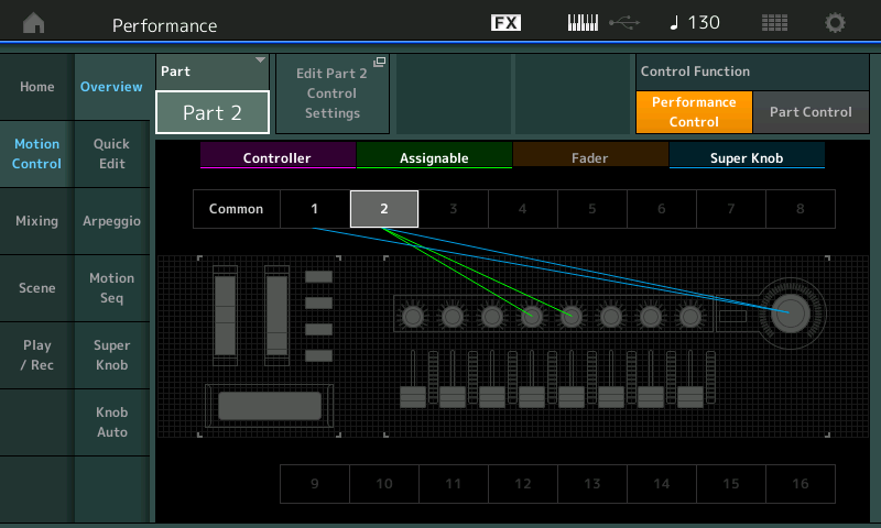
We also learn, by selecting “PART 2”, that PART 2’s AssignKnob4 and AssignKnob5 are under control of the Super Knob:
The OVERVIEW is one way to see this, although the actual Controller assignment takes place on the “Edit – Common/Audio” > “Control” > “Control Assign” screen. Below we have set the DISPLAY FILTER to “ALL” so that we can view multiple assignments simultaneously. Four Destinations of the sixteen available for this level of Editing are shown at a time.
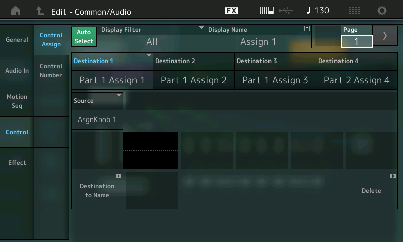
To see the next four locations, advance the PAGE to PAGE 2:
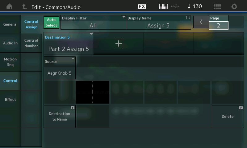
The five Destinations are as follows:
PART 1 Assign 1.
PART 1 Assign 2.
PART 1 Assign 3.
PART 2 Assign 4.
PART 2 Assign 5.
As you can see, the Part Assignable Knobs are all assigned to corresponding Common Assignable Knobs. This allows individual control of each assigned parameter.
Because these assignments are basically made as you develop your ideas about what you want to accomplish, you will naturally start by assigning individual controls to a knob, but recognize that it can get as complex as you desire. Multiple destinations can be assigned to a single knob. This is important to mention here because often you may be using two similar PARTS to create a LEFT and a RIGHT version – and will want to use a single Knob to control both together. We’ll get to that in a future article, but it is important to mention that you have the choice!
To locate what is shown above, from the PERFORMANCE (HOME) screen:
- Press [EDIT] (Edit – Common/Audio).
- Select “CONTROL” in the left column in the screen.
- Select “CONTROL ASSIGN” in the second column.
- Activate AUTO SELECT and turn the first 5 Knobs.
- AssignKnob 1/ Part 1 Assign 1. This is on upper level COMMON/Audio – the overall COMMON Level.
To actually see what the PART 1 Assign 1’s DESTINATION parameter is, you must go to the individual PART EDIT and look at its assignment.
Assigning the functions to individual/separate Knobs is not necessary. It would also be possible to assign more than one Part’s Assignable Knob to the same Common Assignable Knob, or you can assign several parameters to the same knob on the Part Control screen – it’s really up to you. The consequence of combining multiple parameters to a knob is that they will share the overall range and direction of movement, although this can be adjusted/compensated for at the parameter assignment. How you assign items to Knobs, and whether they are individual or grouped, is a production decision/preference.
Part 1 of this example includes a percussive analog synth sound, which is faded out (volume) by moving the Super Knob to right. At the same time, the Filter Decay Envelope gets longer (FEG Decay1) and the Reverb Send increases.
Highlight each of the DESTINATIONS 1, 2 and 3 in turn to view the SOURCE, CURVE TYPE, POLARITY, RATIO and PARAM 1 (curve dynamic) for each assignment.
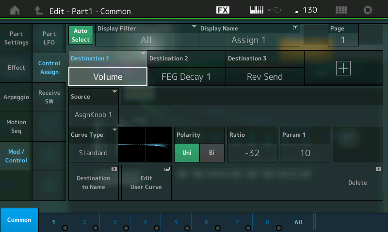
As shown in the screenshot below, you can view the three PART1 assignment Destinations simultaneously by setting the DISPLAY FILTER = ALL.
Hint: You can [SOLO] PART 1 or simply [MUTE] PART 2. As on the Motif, buttons 1/1 through 8/8 are SELECT and the buttons directly below (1/9 thru 8/16) act as MUTE/SOLO. By isolating just PART 1 you can hear how turning ASSIGN KNOB 1 turns down PART 1.
Notice that the RATIO is -32 (negative values reduce), and the PARAM 1 function (10) is the CURVE you are hearing – changing this to anything else will make this clear. Please experiment. When PARAM 1 = 0, notice that the reduction in volume is practically immediate. PARAM 1 = 5 is basically linear
Five of the SUPER KNOB functions are listed in the upper COMMON level – three to PART 1 and the last two (KN4/KN5) that are affecting PART 2. These are seen by selecting PART 2 and viewing its individual PART CONTROL > CONTROL ASSIGN.
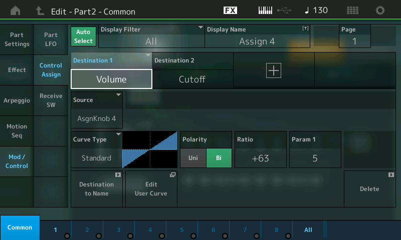
Part 2 includes a fat, stacked trance pad sound, which is faded in by moving the Super Knob to right. Filter modulation begins as you move the Knob from the center position:
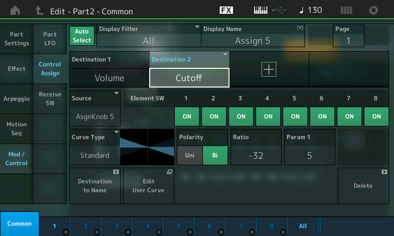
PART 2 – DESTINATION 2 Cutoff (Assign Knob 5). As you turn the Super Knob clockwise, you close the FILTER for all Elements:
Press [PART SELECT 2/2]. Nothing is assigned to PART 2 for Knobs 1, 2 and 3, but KNOBS 4 and 5 are set to VOLUME and CUTOFF.
You can isolate PART 2 and listen to how individual Knobs 4 and 5 interact with PART 2.
Notice that in the Destination Volume screen, this is COMMON VOLUME and so it affects all Elements. Destination 2 on the right (Cutoff) is a destination that can be switched per Element (similar to the Motif Control Sets).
Explanation: The Common VOLUME parameter turns all Elements in this PART up or down together. If you want to instead control individual Elements, you would target “Element Level,” not the Common Volume. Since each Element has its own FILTER and therefore its own CUTOFF setting, you can opt out or opt in on a per Element basis when you are dealing with this setting. The MONTAGE will show you the Element Switches based on the DESTINATION parameter in question.
Catch up on the previous article in the series – “Mastering MONTAGE 5: Super Knob Morph” here.
Next article: “Mastering MONTAGE 7: Super Knob Value Ranges” is here.
Keep reading