Let’s continue our “deep dive” into the functionality of the MONTAGEwith lucky lesson #13.
(NOTE: The Live Set used in these tutorials can be downloaded here.)
Here, we’ll be talking about the MONTAGE Assignable Function buttons. These were introduced back in 2007 when the Motif ES evolved into the Motif XS. The [AF1] and [AF2] buttons had a dual role: They were available within the Control Set to act as a switch for those parameters requiring this type of control, but they were also given a new performance enhancing role where they controlled XA CONTROL (Expanded Articulation) Control functions.
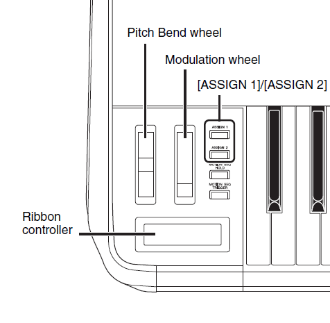
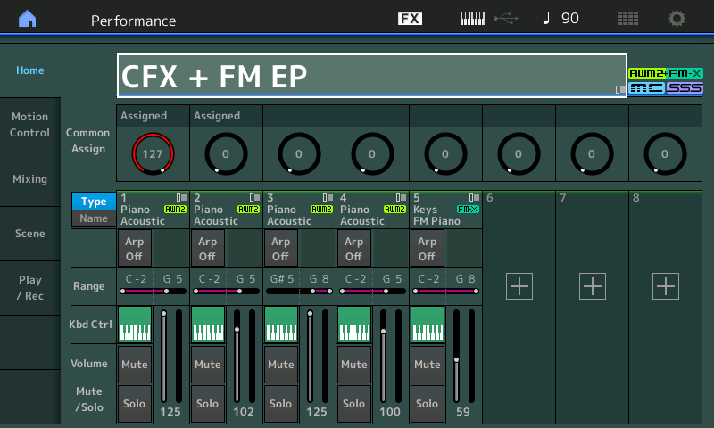
In MONTAGE, these are now referred to as Assign Switch 1 and Assign Switch 2. If you see a Part with a name including “AF1”, “AF2” or “AF1&2”, it will be referring to these two switches located just to the right of your Modulation Wheel, as shown in the illustration above.
Like typical switches, they can be used to send ON or OFF messages, and can be momentary (where, like a sustain pedal, you must hold it for it to take effect) or latched (where they work like typical light switches – that is, they stay on until pressed again). This momentary or latch behavior is programmable on a per PART basis so that each can react as you expect. – you decide based on how you wish to perform the articulation. A good example would be some of the acoustic guitar Performances (such as “Steel Twin Gallery”), where Assign Switch 1 is used as a momentary switch to bring in a harmonic, and Assign Switch 2 is used to articulate a muted note. The String Orchestra Performance “MediumLargeSection” provides a good example of the latching function. Here, engaging Assign Switch 1 changes the Element set that is playing from the bowed orchestra to a pizzicato articulation – the latch setting is more appropriate for extended play.
Studying the Preset Performances, knowing what to look for, and where to find it, is quite important when it comes to the Assign Switches. They can be used within the PART setup to flip/switch any available parameter – bring in an effect, change speed of an effect parameter, etc., but also can be used as a musical tool to expand your performance palette. The XA CONTROL – the way that different articulations can be recalled instantaneously and smoothly “knitted” into the sound you are performing – is designed to be musically invisible. These functions are assigned on a per AWM2 Element basis and include: Normal, Legato, Key Off, Cycle, Random, Assign Switch Off, Assign Switch 1 On, and Assign Switch 2 On.
Normal – The Element will sound when the Note Limit, Velocity Limit and other programmed requirements are met.
Legato – The Element will only sound when the Part is set to mono and a legato gesture is used on the keyboard. If a new key is pressed before the original is released, then and only then will the Element sound. When the Element’s Waveform excludes the attack portion of the instrument, you can get a more natural legato phrase. For example, a flute sample is typically recorded with the attack of the note, making it impossible to play a legato phrase with samples. The Legato XA Control feature allows the legato performing gesture to recall an entirely different Waveform – one that is without the attack portion of the wave (the sampled data is offset so the player’s attack is not included). The synth engine will then “knit” this waveform into the sounding phrase. This allows more natural phrasing when attempting to play fluid woodwind and horn sounds, and can be used to great effect on lead sounds like electric guitars as well.
Key Off – The Element will only sound when the Key is released or the sustain pedal is released. This is typically used to recreate the sound after the release of the mechanism. In a piano, for example, it’s used to recreate the noise of the hammers and the re-engaging of the felts. Noise that happens on release can be “knitted” onto the currently sounding Elements with the XA Control.
Cycle – The Element can be set to a “Element Group” number, where Elements with the same Group number will interact. Instead of all being triggered simultaneously, you can set the Elements to sound one after the other. Grouping Elements can create a situation where it cycles between the groups.
Random – Here, the Element behavior is like Cycle, but the Elements within the Group are selected randomly rather than in numerical order.
Assign Switch Off – The Element will only sound when both Assign Switches are OFF.
Assign Switch 1 On – The Element will only sound when Assign Switch 1 is ON. Assign Switch 2 On – The Element will only sound when Assign Switch 2 is ON.
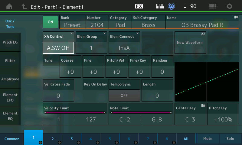
To navigate to the screen where the XA CONTROL is assigned, you must first select an individual Element within the AWM2 PART:
Press [EDIT].
Press [PART SELECT 1/1].
Select Element 1 for Editing by either touching “1” along the bottom of the screen or by pressing the ELEMENT [1] button on the right front panel.
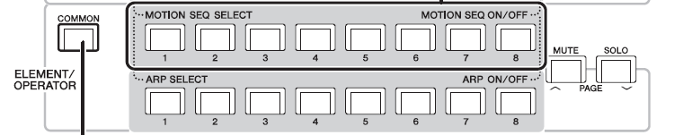
The next to bottom row of buttons are ELEMENT/OPERATOR SELECT 1-8 when you are in EDIT.
The bottom row of buttons are ELEMENT/OPERATOR MUTE/UNMUTE 1-8.
Think Outside the Box
The Assign Switches can be used to switch not only between Elements within a PART, but also between entire PARTS of a PERFORMANCE. In other words, if you have a multi-Element string Part, you could set the XA CONTROL function so that it only sounds when both ASSIGN SWITCHES are OFF. Then, when you engage Assign Switch 1, you could program a Brass Part to play. This means that, while playing the Strings, simply pressing Assign Switch 1 would change the next notes you play to a Brass sound. Best of all, this is a musically invisible change: no notes get cut off, and there are no glitches.
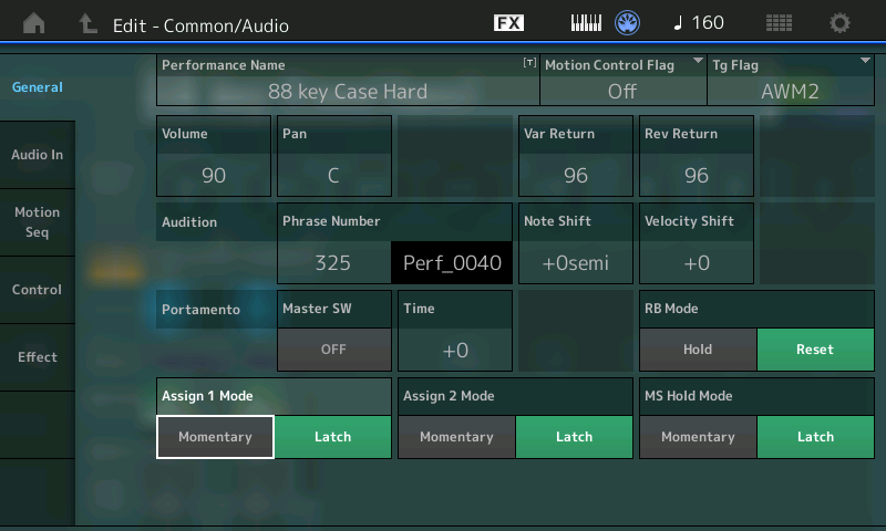
The Assign Switches can be set as Momentary or Latch for the PART. This is found on the upper “Common/Audio” level. The example shown below is from the PERFORMANCE “88 key Case Hard” Electric Piano PART:
Press [EDIT].
Press the upper [COMMON] button.
Select “General” in the first column in the screen:
Momentary and Latch can be selected for each of the assignable buttons.
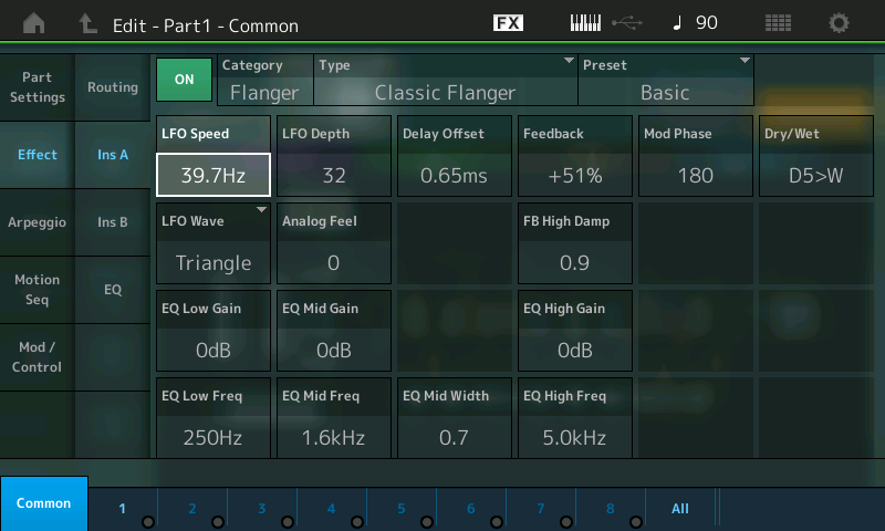
In addition to the dedicated XA CONTROL, the Assign Switches can be used as a SOURCE in a PART’s “Mod/Control” assignment box. This can flip an Insert Effect parameter from one condition to another – useful for activating effects in real time.
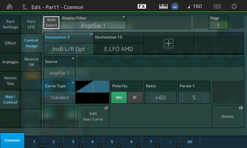
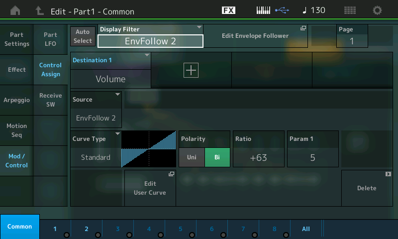
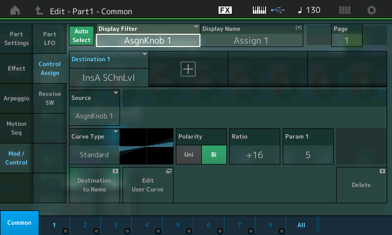
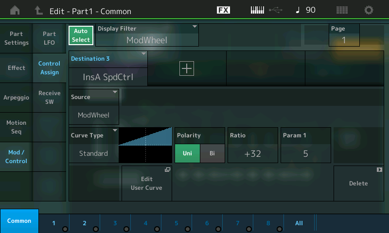
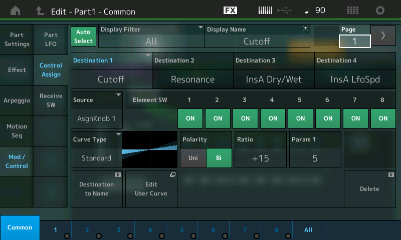
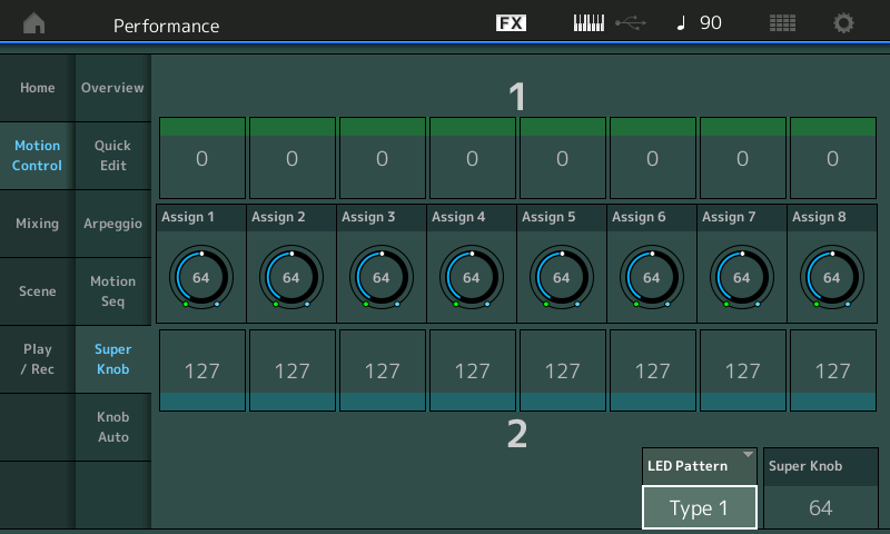
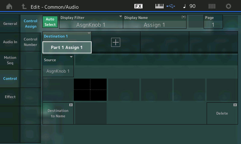
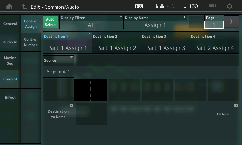
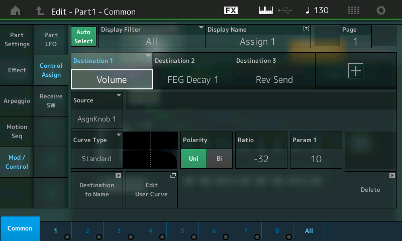
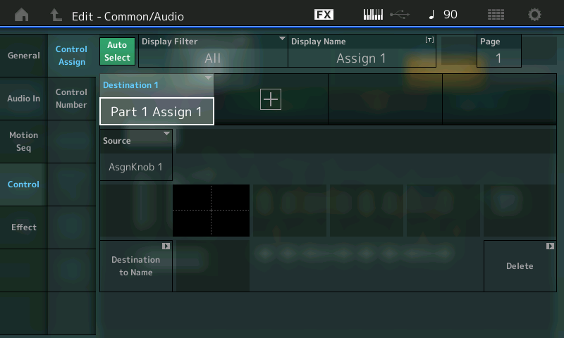
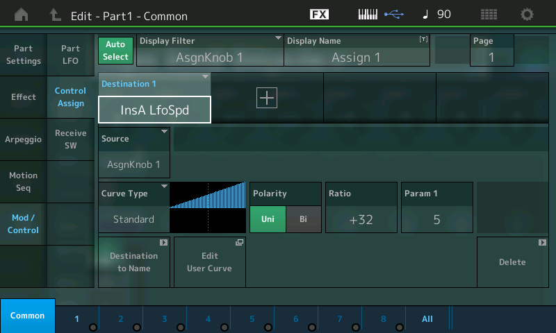
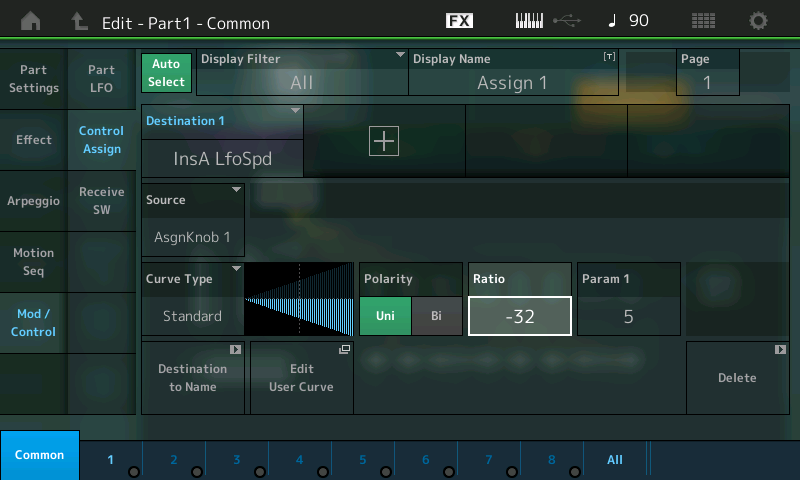
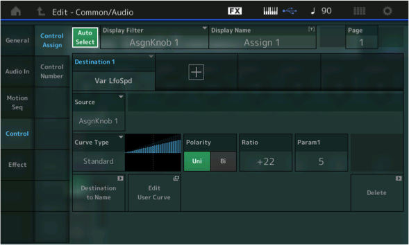
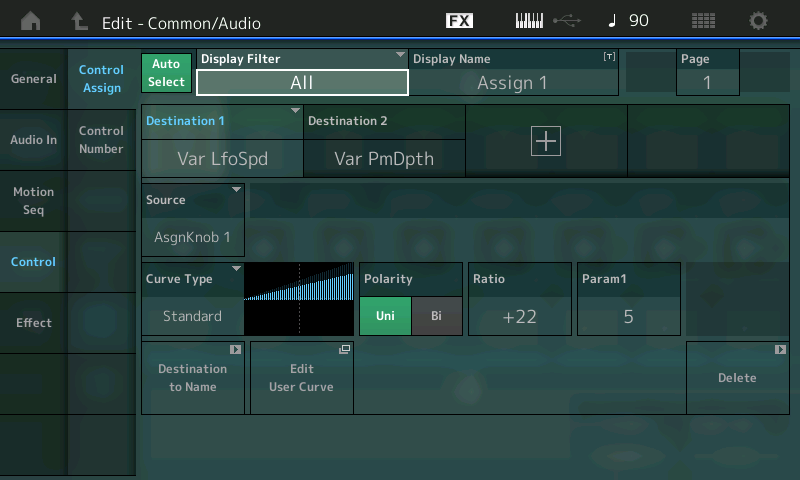
When assigned in the Control Set, the Assign Switch will glow, indicating that something is assigned to the Switch. In order to hunt down and discover what exactly is assigned to a particular Switch, the AUTO SELECT feature can be useful. The Display Filter allows you to view what is assigned to a specific controller – you can either manually set it to view a particular controller, or you can activate the AUTO SELECT (green) box, which will let you touch the control to change the view.
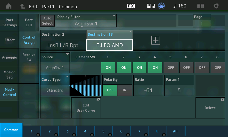
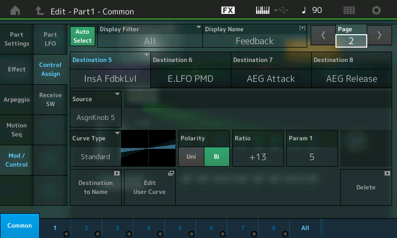
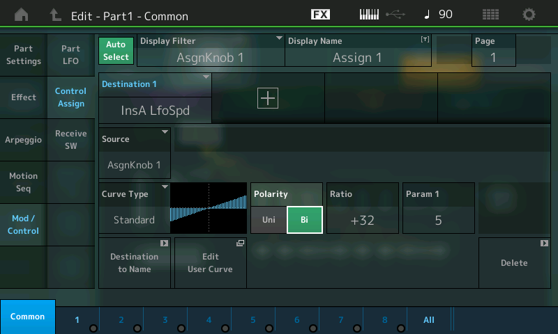
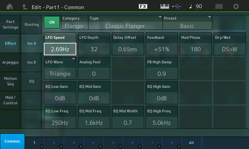
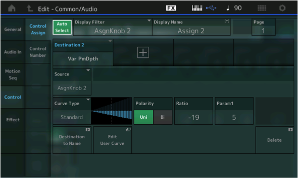
In the screenshot above, the Display Filter is set to limit the controller assignment view to just those things assigned to AsgnSw 1. In other words, for this particular PART, Assign Switch 1 is being used to control INSERT EFFECT B’s “Left/Right Pan Depth” by taking it from its current setting to maximum (i.e., Off to On). On this particular Electric Piano Part, this is used to bring in the AUTO PAN Left/Right movement – a typical use case of OFF to ON status. In addition, by moving the highlight to the Destination 13 box, we can view another Assign Switch 1 destination:
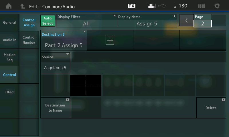
Here it is assigned to change the Element Low Frequency Oscillator responsible for Amplitude Modulation Depth from its current state to OFF for Elements 1, 2, 3 and 4.
Young percussion students who are studying with a private instructor usually study solo on marimba, snare drum, drum set or timpani. Ensemble playing techniques are usually something that are acquired later in high school – and unfortunately, the percussion section doesn’t usually get as much attention as it should. Yet percussionists are required to know how to play a vast array of instruments, as well as the techniques that are associated with them.
Here are the “Top 10″ things all percussionists should know before going into their first ensemble rehearsal. Hopefully this list will help you make the transition from solo to ensemble easier.
1. Bring one (or more) black towels.
A black towel is a wonderful thing. It can be used:
On a music stand to create a stick tray.
On a bass drum or tom to mute the drum.
To wipe sweaty hands.
2. Every note you play is a solo.
Play with confidence and don’t hide the instrument behind the music stand.
3. Photocopy your music if you are playing from more than one music stand.
Do not move the music from one stand to another. Also make sure your music is taped together so it doesn’t fly off the stand when the AC is turned on or the side door suddenly opens.
4. When you have rests, REST.
Don’t look around. Don’t check your email. Don’t text. Don’t talk to other people in the section. Count your rests and come in on time when it is your turn to play.
5. Listen to the sound you are getting on the instrument; don’t just “hit the drum.”
Enough said.
6. Vibes and marimbas are generally going to be lost in the texture of a large ensemble, especially a wind ensemble.
Xylophone and Bells are not! When you are playing vibes or marimba, use a slightly harder mallet than you think you should and ask someone to go out to the audience during the rehearsal to check the balance.
7. Learn to play triangle softly with a large beater.
Your goal is to excite as many overtones as possible. A smaller beater only produces a thin sound.
8. Always warm up the tam tam before playing.
Also, stand on the side of the instrument when playing it (not in front).
9. Breathe before you play, especially if you have a full ensemble unison.
Again, enough said.
10. The conductor is always right (even if they are wrong).
Do what the conductor wants and don’t talk back – the conductor is in charge. If they ask for a different mallet or instrument, GET IT. Remember, the conductor can hear everyone in the ensemble when they play together and knows what is needed to make the team effort sound just right. Don’t talk to them after rehearsal about what beater is required. If they want something different, they will ask you about it or they will come to find you to talk about options.
This list is in no particular order – they are all equally important when playing in an ensemble. Am I forgetting something? If you are an instructor/conductor, are there any more things you tell your students before their first ensemble rehearsal or something you have observed that you think everyone needs to know?
With long nights on a bus driving to the next performance, early morning wake-up calls and humid days on the football field in rehearsal, the last thing a drum corps, high school band or any other musician needs to worry about is instrument reliability. Yamaha tests its percussion products extensively with numerous drum corps so that students and band directors have one less thing to worry about.
Take, for example, the famed Madison Scouts Drum and Bugle Corps, with whom the Band & Orchestral Division of Yamaha Corporation of America have been partners for over 30 years, marching in step to make great music. “May you never walk alone” is the apt creed that typifies the 67-year history of the Scouts, and anyone who has taken part in the intense camaraderie and creativity of such a group can understand just how deeply it runs.
Since first forging the partnership in 1985, the Madison Scouts have used Yamaha percussion instruments exclusively, but that is only the beginning. The Corps has also lent its expertise to the testing of many of our products in the rigors of an outdoor setting, and has contributed directly to the development of several landmark Yamaha instruments and accessories, including the sfz™ snare drum, stronger tenor and bass drum lug casings, deep cut tenors, the MTS snare drum, different types of Acoustalon™, outdoor keyboard frames such as the Multi-Frame I and Multi-Frame II, concert bass drum stands, stadium hardware, and drum covers and carriers.
An estimated 1,700 young Madison Scouts percussionists have used Yamaha instruments since that time, benefiting not only from the use of the equipment but from a constant supply of advice and support from the people who create it. “The kids in the corps throughout the years have always been grateful for Yamaha’s support, and it has really enhanced their experience performing on state-of-the-art instruments,” reports Jeff Moore, former Scouts percussion arranger and director, adding, “these young men have never taken it for granted.”
Relationships are at the core of our lives and everything we do each day. They are not something easily made, but with a lot of hard work can grow to become something wonderful and meaningful. The Madison Scouts and Yamaha have enjoyed such a relationship for over thirty years. We are looking forward to the next thirty!
MONTAGEMotion Sequences are tempo-synchronized, completely customizable control sequences that can be assigned to virtually any synthesizer parameter – meaning that they provide extremely creative new ways of programming sound. In this lesson, you’ll learn more about how the dedicated Motion Sequence controls on the MONTAGE front panel make it easy to manipulate and change sounds in real time, adding powerful interactivity and expression.
(NOTE: The Live Set used in these tutorials can be downloaded here.)
Background and Theory
Before we begin, let’s take a moment to explain some new terminology. While the concept of a sequence is clear to most of us, what actually is a “Motion Sequence”? We think of sequences, like arpeggios, as consisting of notes. In the Motif series, however, you could select arpeggios that were made up of controller messages instead of notes. These so-called “Control Arps” applied changes to the notes you played. Some might rhythmically adjust volume or pan position, while others added pitch bends or made changes to filter cutoff and/or resonance. This is a good background for gaining an understanding of Motion Sequences.
Like Motif Control Arps, MONTAGE Motion Sequences do not consist of notes. Instead, they are automation for parameter controls – and the way you to decide to use them is wide open.
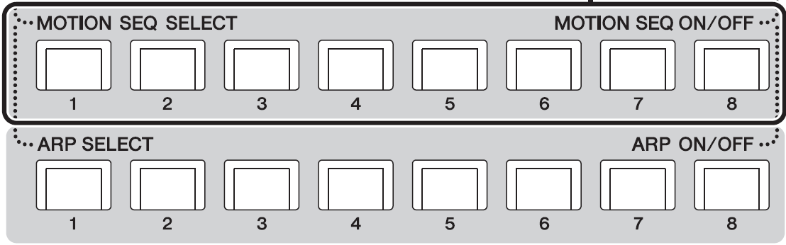
The comparison to Arpeggios is very on-point, as there are eight Arps and eight Motion Sequences accessible via the bottom two rows of MONTAGE front panel buttons:
These can be paired and recalled in tandem, and can be assigned, in any order, to any one of the eight SCENE buttons.
[SHIFT] + [SCENE 1-8] registers the selected Motion Sequence or Arpeggio to a [SCENE] button.
KEY THINGS TO KNOW
Please take a moment to read through pages 78-84 in the MONTAGE Reference Manual (downloadable here) to familiarize yourself with basic Motion Sequencer terminology and structure:
A MOTION SEQUENCE is a series of up to 16 steps – it can be as short as one step or as long as 16 steps.
Each Step has an amplitude setting and can be extremely complex.
A MOTION SEQUENCE can be set to Loop, or to play when Triggered (like an Arp).
A MOTION SEQUENCE can be be adjusted as to timing, intensity and feel (also like an Arp) via MS FX.
A LANE is a pathway to a specific parameter or multiple parameter destinations.
You can assign up to eight desired Motion Sequence types for any one LANE.
You can also set up to four LANES for one Part.
Up to eight LANES can be used simultaneously for the entire Performance.
You can construct Motion Sequences manually or you can select from a variety of preset Sequences. They can be adjusted, shaped, and interacted with in real time, as they happen – and the shapes and nature of these Sequence steps are wildly and deeply programmable.
For example, Motion Sequences can be set to loop, or they can be triggered manually as “one shot” phrases, or retriggered at each key-on, or just played from the very first key-on, etc. They can be synced to tempo or they can be set to divide or multiply the current tempo (stretching out to some 64 measures). They can follow the arpeggiator and start when it does, or they can run freely. Tempo and timing offsets can be applied (like PLAY FX in the Motif XF), allowing great flexibility in how they “feel” when applied to the synth. You can also sharpen and/or amplify their influence on the target.
Motion Sequences can certainly be used in rhythmic ways – the obvious and typical example would be a very rhythmic movement of the cutoff frequency, or rhythmic pulsing when assigned to volume or pan position. But the assignments go way beyond these typical uses because they can manipulate a wide palette of parameters – even parameters that control other parameters. And since they can reference tempo, or be manually triggered, you can use this feature to accomplish all kinds of musically related automation. The ability of MONTAGE to link with and derive tempo from external devices means that it can play Motion Sequences that are “tempo/measure aware” of its surroundings. You can also use Motion Sequences to add a single change event that occurs at set intervals – many times events are set to occur at four, eight, 12 or more measures; the Unit Multiply setting allows you to change how your Sequence references the Tempo. Unit Multiply = 100% would make 16 steps equivalent to one measure. You can expand this reference out to 6400%.
PERFORMANCE 15: Motion Sequence 1
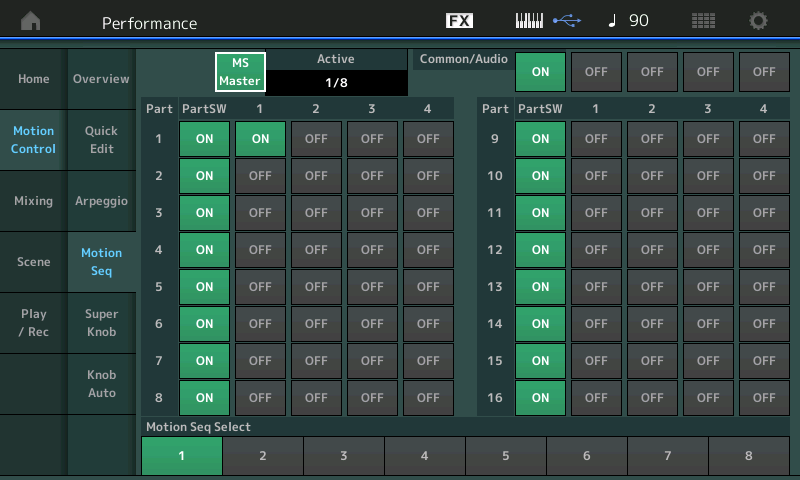
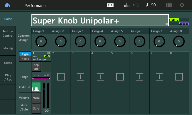
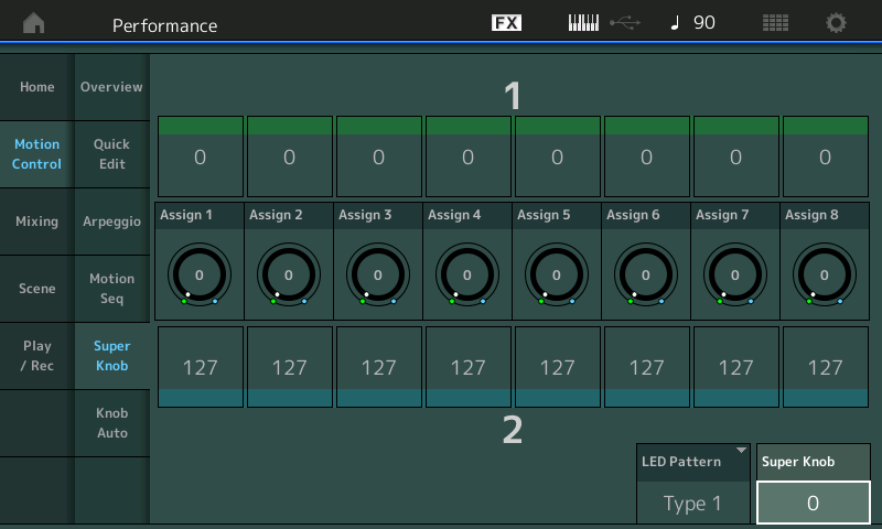
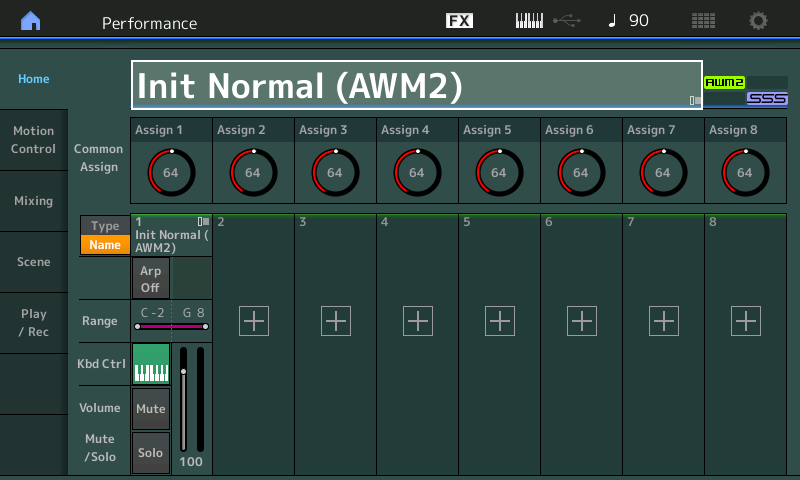
From the PERFORMANCE (HOME) screen touch “MOTION CONTROL” > “MOTION SEQ”. Here you will find the “MS MASTER” switch and an overview of the various PART SWITCHES:
The PART SWITCH for each of the 16 Synth Parts defaults to ON. You must additionally activate a LANE for anything to happen.
The MS MASTER (Motion Sequence Master) Switch is repeated in this screen and this operates the front panel button’s On/Off function. (The Master ARP ON/OFF and MS ON/OFF are adjacent to each other on left front panel next to the SCENE buttons.)
In the screenshot above, you can see the four Lanes available per PART. In total, there are 64 LANE switches – the “ACTIVE” box counts how many of the eight simultaneous LANE switches are currently active. Only PART 1 has a Lane Switch active in the above shot, so one of eight is shown as Active; i.e., “1/8”.
Actually, there can be 8+1 Lanes active. The “+1” refers to the dedicated Motion Sequence available for automating the Super Knob movement. (More on this below.)
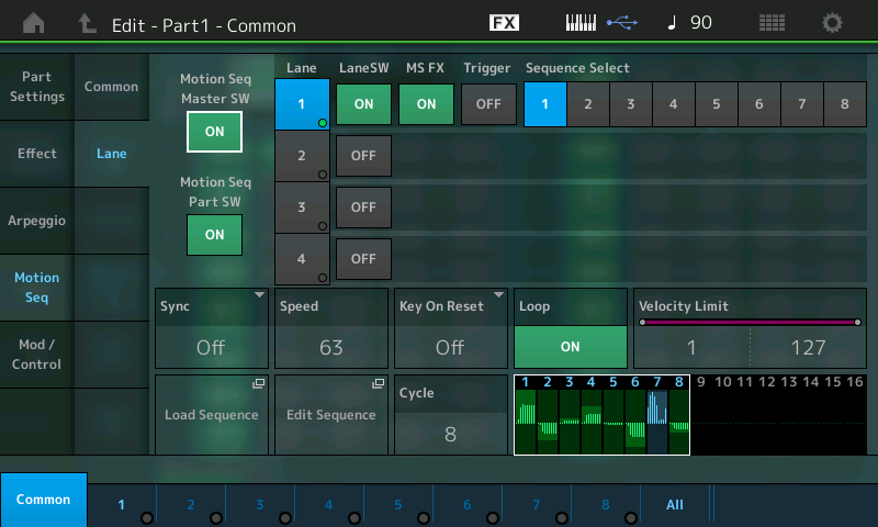
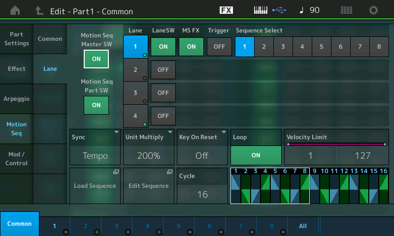
When you drop into the PART level of editing for MOTION SEQ > LANE, you’ll see that, in this example, only LANE 1 is active (blue LANE 1). MS FX is ON, which allows timing offsets to be applied. Here, we are viewing Sequence #1 of 8 possible sequences:
Press [EDIT].
Press [PART SELECT 1/1] to view PART 1 parameters.
Touch “Motion Seq” > “Lane”:
Shown above is the “Edit – PART 1 – COMMON > “Motion Seq” > “Lane” screen. Here you will find the Master Switch for the Motion Sequencer (repeated) and the PART Switch, repeated as well for convenience. Notice the Shortcut Boxes to “LOAD SEQUENCE” and to “EDIT SEQUENCE.”
It’s critical that you make the Destination assignments in the Part “Mod/Control” box because, without a parameter Destination, the Motion Sequence does nothing. Remember, it’s controller data – not note data – and so it needs a Destination to manifest its influence. This is a very important concept to understand. Say the Motion Sequence is a series of values that decrease and then increase: until you assign it to a parameter (Destination) it is meaningless. If it is assigned to a LPF’s cutoff frequency, however, then you will hear it manifest itself by changing the timbre of the synth on the notes that you play. For example:
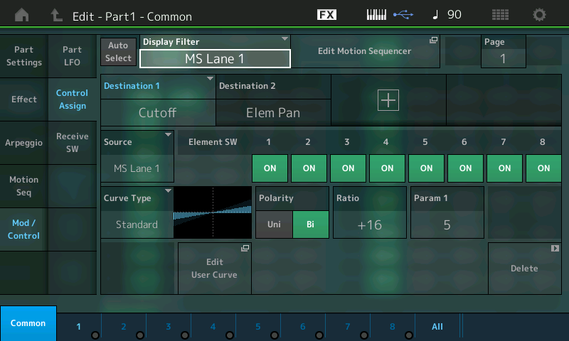
Touch “Mod/Control” > “Control Assign”.
The DISPLAY FILTER is highlighted and “MS LANE 1” is selected.
You can see the Destination 1 = Cutoff, and Destination 2 = Elem Pan:
We start here with two very obvious Destinations – easy to hear and recognize. Increase the Ratio to get a sense of what is being changed.
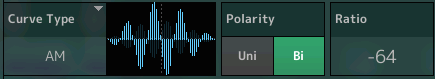
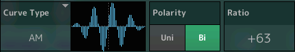
Polarity is set independently for each to BIPOLAR because we are offsetting the cutoff frequency above and below a normal setting; with pan we are moving right and left from a center position. Switch between Destination 1 and 2 and adjust the Ratio amount, then listen to the changing influence.
Note: In this example, the used Control Sets are both routed as follows:
Source: MS Lane 1 > Cutoff.
Source: MS Lane 1 > Element Pan.
It’s possible to assign more than one parameter to a Lane: Simply touch the “+” ADD icon to add a new Source/Destination setup.
The significance of being able to select “MS Lane” as the SOURCE means that you can group your automation shapes. In a Part with multiple Elements, for example, a Lane could be assigned to influence Elements 1-4 to create coordinated movement in both filter cutoff and pan position, while a second MS Lane could be used to automate contrary movement in Elements 5-8, or move at slightly different rates and directions. Hey, that’s why they call it a synthesizer!
Touch the box next to the DISPLAY FILTER called “Edit Motion Sequencer” to take the shortcut to the currently selected Motion Sequence.
For this example we only need Lane 1, which uses these settings:
As mentioned, each Part includes eight Motion Sequences, numbered 1 – 8. These can be selected for playing by the MOTION SEQ SELECT buttons on the panel when performing, or by the SEQUENCE SELECT buttons while on this EDIT screen.
For example, if you switch to SEQUENCE SELECT number 2, you will receive a new set of four lanes with completely different Motion Seq steps, Curves and other parameters. But please remember the limitation of a maximum 8 Lanes simultaneously. Later in this tutorial we’ll take a look at a PERFORMANCE that uses all eight Lanes of assignment.
You’ll find that you will not always need several Lanes for a Motion Sequence because you can assign more than one parameter to a Lane. Nonetheless, it can be extremely interesting to use different Lanes for specific control assignments. Using the UNIT MULTIPLY feature, you can space events out over entire sections of music. If you think of the 16 Steps as one measure, this equates to UNIT MULTIPLY of 100%. As mentioned above, you can expand the time out to 6400% (64 measures). Your mileage will vary.
The ramification of assigning more than one parameter to a Lane is that it will follow the same control movement, which, musically speaking, can be just fine. That’s because the degree of response is individually programmable. In our example, both Cutoff and Element Pan share the same Lane, but each has its own set of “depth” parameters that determine how deeply it gets applied. When creating your own Programs you will have to determine which parameters need to be controlled with their own independent movement, and which can share.
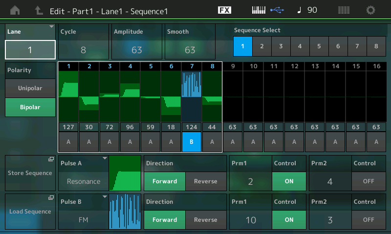
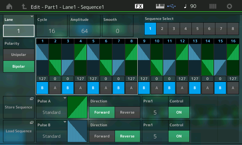
The Steps of each Lane can be deeply edited, too. Notice that the steps are divided into two sets of eight on the screen: 1-8 and 9-16. (A white box in the screenshot above outlines STEPS 1-8.) You can set the CYCLE value to any number of steps for odd time signatures, etc. They are grouped in sets of eight so that you can use the eight Faders and the eight Switches below them to adjust the Amplitude and select the shape Pulse Type A or B in real time.
This hands-on method will allow you to intuitively set accents or swap Pulse Types to create different movements. Rather than step editing by accessing one Amplitude value at a time, you can quickly create Amplitude “shapes” using the Faders. Then you can dial it in by accessing the individual values. Try it: Move the Faders to adjust the amplitude of the corresponding Step and touch the blue SCENE buttons to switch from Pulse A to Pulse B (blue).
Beside setting the values of the steps, the most important thing is to set the Curves and determine their Shape (Prm1/Prm2) separately for the Normal and Accent steps. For example, Resonance is shown for Pulse A, with the Prm (parameter) numbers 2 and 4, with Prm1 = 2 and Prm2 = 4. The two numbers (Prm1/2) are used for distinguishing between the different shapes of a Curve type. Prm1 stands for coarse, while Prm2 provides fine distinctions. You can see what this means by adjusting Prm1/Prm2, both of which help shape the segment.
Prm1 can be set to one of six values: 0 through 5.
Prm2 can be set to one of five values: 0 through 4.
You can also select one of the 18 preset Curve types. Each Curve Bank A/B includes a specific number of curves with different shapes.
The 18 preset Curves are: Standard, Sigmoid, Threshold, Bell, Dogleg, FM, AM, M, Discrete Saw, Smooth Saw, Triangle, Square, Trapezoid, Tilt Sine, Bounce, Resonance, Sequence, and Hold.
The SMOOTH parameter does just what it says: It rounds off the results so you can make sharp, abrupt changes or rolling smooth changes. When SMOOTH is turned down, you will hear more of a radical impact.
The DIRECTION parameter (found in the MS Edit area) selects between Forward and Reverse. For example, in the case of the Resonance Curve type there are 30 possible Curves Forward and 30 possible Curves Reverse.
On the Lane 1 line in the screen above you can see the Lane Switch and the MS FX Switch. The “Trigger” (currently Off) allows you to manually trigger the MS to play as a one time event. You do so by using the dedicated Motion Sequence Trigger button located near your Wheels. Much like Arpeggio Phrases, there are a variety of ways to use a Motion Sequence. Think beyond just “looping” (Cycle) events.
If you want to realize separate Steps and Curve settings for specific parameters, you can use more than one Lane; however, you’ll have to make different control set (Source/Destination) routings for each parameter.
EXTRA CREDIT
Try Loading some of the PRESET CURVES:
Touch the shortcut box “Load Sequence”.
Find the PRESET Folder.
Touch it to open and select “BIG TRIANGLE 4”.
Below I have set SYNC = TEMPO.
UNIT MULTIPLY = 200%.
And the CYCLE = 16 steps:
Touch the “Edit Sequence” box to initiate detailed editing of the Sequence:
Press [EXIT] to return to the”Mod/Control” > “Control Assign” screen and experiment with the parameters. You can clearly see and hear the Filter follow this movement; the Pan also follows this same movement. Visually you can picture the filter closing and opening following this Big Triangle as it makes four trips per Cycle. If you assign it to Pan, then you will hear it manifest itself by moving the signal from hard right toward center and then to hard left. Play with + (positive) and – (negative) RATIO values to hear the change in application.
Just because a Part can utilize four Lanes does not mean you will apply that many to a Part, because a single Lane could be simultaneously changing multiple parameters. In this example, we see the one Lane changing filter cutoff and panning. In many cases, just panning the Element might be enough. Certainly panning, and volume, and cutoff, and LFO speed might be overkill for a single Part, but you could use all four pathways to assign control on this one Part – and that would still leave you four other pathways (Lanes) you could establish elsewhere for this Performance! A study of how MONTAGE programmers use Motion Sequences (MS) will give you a better idea of how to apply this tool. We’ll give you a list of Performances to review at the end of this article.
Sync and Tempo
Sync and Tempo settings for a Motion Sequence can be quite complex.
Sync settings:
Off – not synchronized.
Tempo – references MONTAGE clock settings.
Beat – references internal or external tempo starts at beat timing.
Arp – synchronized to internal/external tempo starts when triggered with Arp phrases.
Note that the “Speed” setting is used only when SYNC = Off.
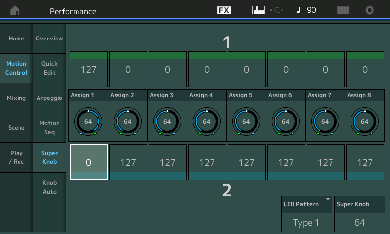
Super Knob Motion Sequence
We haven’t really talked about the Super Knob much in this lesson, but it has its own dedicated Motion Sequence that can be used to automate the parameters assigned to it. This is in addition to the eight Motion Sequences available to the individual synth Parts.
A Super Knob Motion Sequence works basically same way as a Part Motion Sequence. However, assignments in the Controller Box are not necessary because it is simply an automation of the Super Knob movement. Here’s a good way to explore how it works:
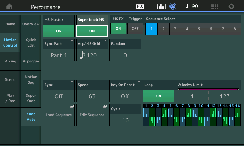
From the HOME screen:
Touch “Motion Control” in the first column
Touch “Knob Auto” in the second column.
Set the SUPER KNOB MS = ON (shown below):
Touch the “EDIT SEQUENCE” box and work with the POLARITY.
If you want to control the complete range of the Super Knob, you need to set POLARITY to Unipolar and AMPLITUDE to 127. For a demonstration, study the “Wax and Wane” Performance.
MORE PERFORMANCES TO STUDY
“Pad Pulsations” – This Performance utilizes the maximum eight Lanes of Motion Sequence… and it has eight different Motion Sequences.
“Motion Filters AF” – Try different Filter automation via the SCENE buttons.
“Pond Ripples” – This Performance uses the Super Knob Auto Play.
“Bit Performer” – This is an example of a Motion Sequence placed on the [Motion Seq Trigger] button.
Catch up on the previous article in the series – “Mastering MONTAGE 11: Envelope Follower” here.
The next article in this series – “Mastering MONTAGE 13: Assign Switch 1 & 2” – is available here.
You’ve invested a lot into your top-of-the-line receiver: the post-dinner evenings spent on the computer researching competing models; the lunch break trips to the local brick-and-mortar electronics store to test out your top three options; and of course, the time it took to convince your skeptical significant other that your decade-old receiver simply had to be replaced – even it if may have had a few years left in it.
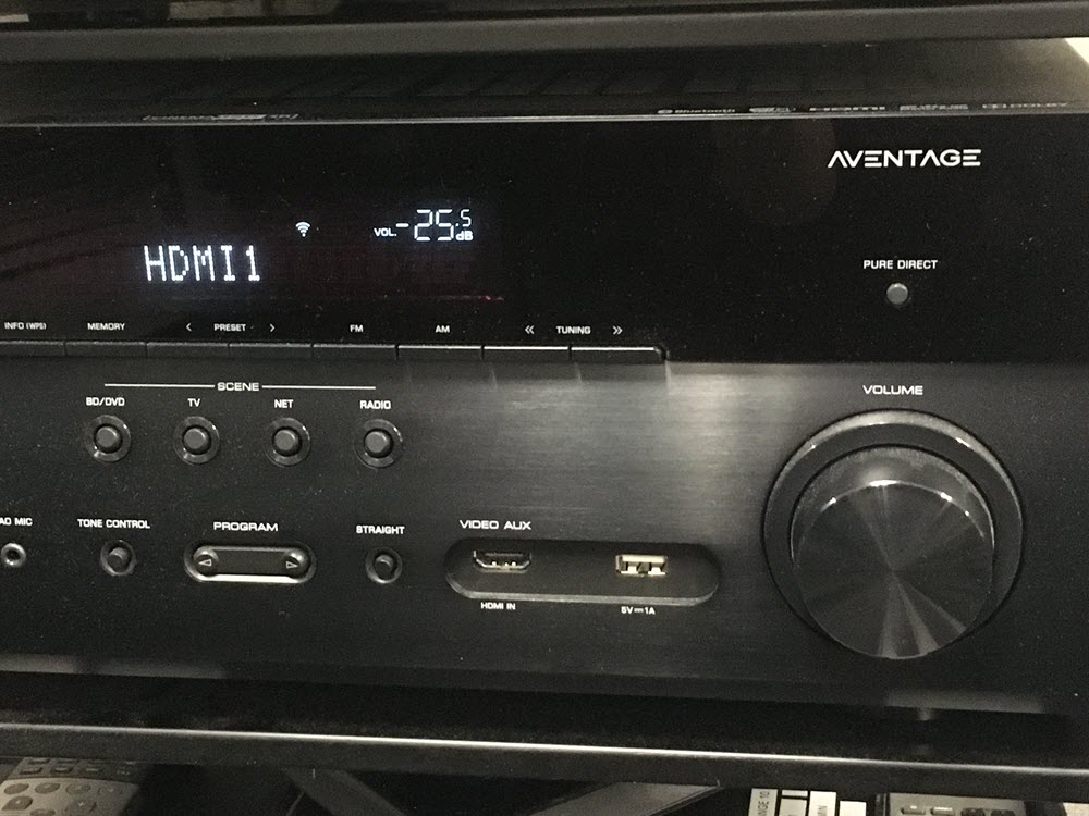
So, you’ve made your choice – a Yamaha AV receiver from the highly rated AVENTAGE line – and got it all set up. Then you notice the numbers on the volume control display are negative. What does that mean?
Negative numbers show the amount of attenuation that the volume control is applying to the amplifier.
Control Volume by Restricting the Signal
Once you get a handle on the explanation, it makes sense. The numbers on the receiver’s volume represent the amplification factor on the signal coming in. For example, when you plug your BluRay™ player into your receiver, the player sends a signal into your receiver’s amp and then to the speakers.
Now imagine an amp with no volume control. It would play at full power all the time. The only way to control the output is to add or connect a volume control.
More Accurate, More Logical
That’s where an attenuator comes in. This is an electronic circuit that acts as a volume control by restricting the amp from playing at full volume and/or power. When you turn up the volume of an amp you are actually decreasing the amount of restriction placed on that amp and in turn it plays louder. The negative number scale is a more accurate way to indicate the volume output.
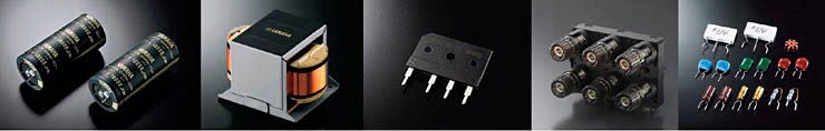
In addition to the amp and attenuator, every single part in a Yamaha AV receiver affects sound quality, such as (L to R): custom made block capacitors, extra-large power transformer, barrier diode, large size speaker terminals and high quality parts.
You also likely noticed the “0 dB” (decibel) setting on the volume panel display. As you know, decibel is the unit used to measure the intensity of a sound. So how does this correlate to your AV receiver’s volume control settings?
Understanding the “0 dB” Setting
As counterintuitive as the negative numbers setting may appear, the Yamaha volume control is actually more accurate than most volume dials.
Think of 0 dB as maximum volume. For example, if your receiver reads “-25 dB” it means that the volume of the signal has been attenuated by 25 dB (that is, made 25 dB quieter than the loudest it could possibly be) before being output to your speakers.
Negative numbers mystery solved!
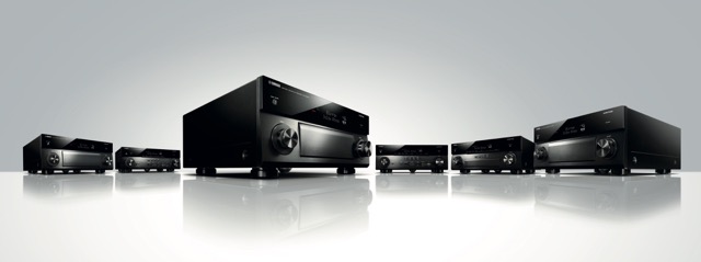
The AVENTAGE line of high-performance AV receivers are designed to provide full-bodied audio for movie sound effects and the accurate reproduction of music sources.
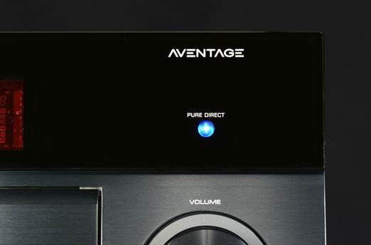
Your music sounds awesome: deep, intense, immersive. It’s hard to imagine it sounding any better. Until, that is, you discover Pure Direct: Pure. Powerful. Better.
The Ultimate in Sound Purity
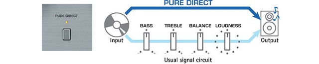
Pure Direct mode is a feature offered by many Yamaha receivers. When engaged, it feeds sound directly to the amplifier and bypasses any DSP processing that might otherwise color the signal, ensuring the best possible high-fidelity sound from all audio sources – even USB and HDMI inputs. The end result is a more realistic sound and a deepening of the listening experience, making it more enjoyable than ever.
Does Pure Direct really matter all that much? If you love music and movies, absolutely!
There’s something almost indescribably awesome about creating an authentic movie theater experience in your own home. It’s convenient, comfortable – and best of all – your own. You get all the fun choices: Do you want a simple setup with just a few AV devices in your living room or a complex one that rivals local multiplex cinema? And you get all the challenges, too.
Making the Most of Your Movies
One of the most common issues would-be home theater enthusiasts encounter is space: Many people simply don’t have an area dedicated solely to the home theater of their dreams, and even a basic 5.1 channel set up can take up a lot of real estate. That’s not a problem with Virtual CINEMA FRONT, exclusively from Yamaha.
Virtual CINEMA FRONT is featured in the AVENTAGE line of receivers and other Yamaha AV products.
Surround Sound Benefits
In the Virtual CINEMA FRONT setup, you can place all five speakers and a subwoofer at the front of your room. Wire your speakers to your Yamaha receiver, then activate the built-in YPAO™ (Yamaha Parametric Acoustic Optimizer) to ensure that the listening area is tuned to provide the best audio experience possible.
The speakers project the sound onto the walls, creating a surround effect that is nearly indistinguishable from having real speakers in the back of the room.
Virtual CINEMA FRONT technology makes creating your own little slice of home theater heaven easier and more convenient. So whether you have an entire room to fill with AV gear – or just a corner of the living room – you can enjoy the benefits of surround sound.
Into percussive arpeggios and drum grooves? This lesson is for you!
(NOTE: The Live Set used in these tutorials can be downloaded here.)
The MONTAGEEnvelope Follower allows you to use the output of a Part for modulating selectable parameters of any other Part, enabling you to transfer the movement or rhythm of a Part to other Parts. This way of shaping sound works especially well with percussive arpeggios and drum grooves.
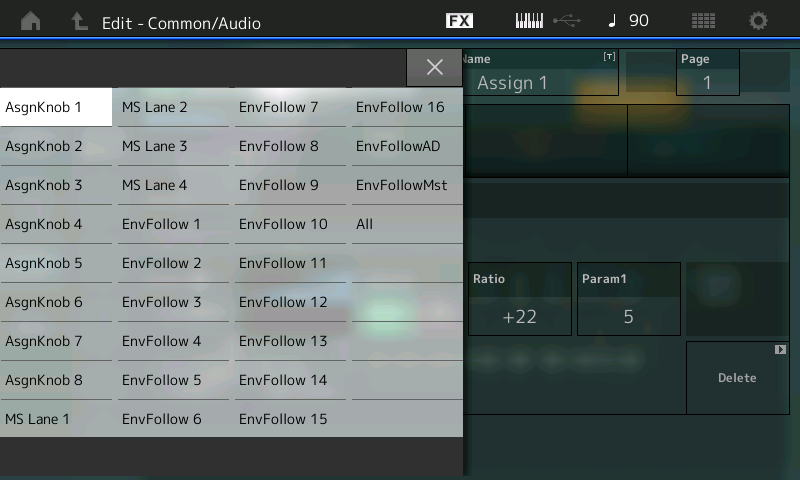
In the Controller Assign box you will find the sources named “Envelope Follower 1 – 18”.
The numbers 1 – 16 are assigned to Parts 1 – 16, while the numbers 17 and 18 are assigned to the A/D parts (L+R).
An Envelope is used to describe a shape. In synthesizers we talk about three main components: Pitch, Timbre (filter), and Loudness (amplitude). There are Pitch Envelopes, Filter Envelopes and Amplitude Envelopes. “Shape” is simply a way to describe how they behave over time: how they start, what they do while they are happening and how they disappear. In the case of the MONTAGE Envelope Follower we are using the Loudness (Amplitude Envelope) of one Part’s sound to create an attack-decay-sustain-release shape for another Part to follow. In other words, the Source Part creates the envelope, while the Destination Part follows that shape.
In our last lesson, we saw an example of how Side Chain Compression uses one sound to replace or “duck” the volume of another. Here, one sound will follow the shape of the other so the pulsing nature of a drum groove can cause the affected sound to exactly follow the rhythmic movement.
PERFORMANCE 14: Envelope Follower
In this example, a Synth Comping sound in PART 2 is used to influence a Synth Pad sound in PART 1. The Synth Comping sound is under the control of an arpeggio’s pulsing techno groove, which triggers the Synth Pad to increase in volume.
For using the Envelope Follower you simply have to make one control assignment for the Part that receives the modulation. In this example, this assignment is found by editing PART 1’s Controllers.
From the main Performance (Home) screen:
Press [EDIT].
Press [PART SELECT 1/1].
Touch “MOD/CONTROL”.
Touch “CONTROL ASSIGN”.
Touch the DISPLAY FILTER box to open the LIST VIEW.
Use the DATA WHEEL to scroll down to “EnvFollow 2” (which means that PART 2 will be referenced as the SOURCE).
Here you can see how the VOLUME is being controlled:
In this example, the Dance pad is shaped by the rhythm of the synth arpeggio of PART 2. Selecting the Source “Envelope Follower 2” and the Destination common “Volume” means that the output of PART 2 modulates the Volume of PART 1.
Temporarily reduce the Ratio to 0. This will remove the influence of PART 2 on PART 1 so that you hear the normal steady sound of the pad sound. As you increase the Ratio toward +63, you’ll hear the increased influence of PART 2 on PART 1.
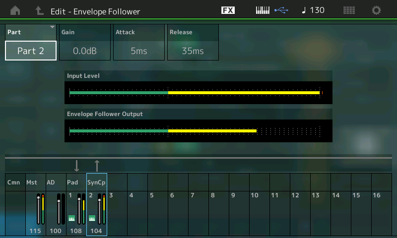
To understand this routing, it’s helpful to navigate to the EFFECT itself. In the screenshot above you can see a box next to the DISPLAY FILTER > EnvFollow 2 that is a shortcut box labeled “Edit Envelope Follower”. Touch this to be taken directly to the Envelope Follower:
In the screenshot above, PART 2 is selected and is identified as the SOURCE. The bottom of the screen shows which Parts are feeding into the Envelope Follower as SOURCES to create the “envelope” and which are set to “follow.” From this it is clear that PART 2 (SynCp) is the source, and PART 1 (Pad) is the “follower.” GAIN, ATTACK and RELEASE all help to “shape” the envelope. Experiment by changing the Attack and Release to hear the resultant effect. Gain simply increases the audio output of the source energy.
IMPORTANT NOTE: It should be mentioned here that the screenshot above allows you to edit the GAIN, ATTACK and RELEASE of the item that you have selected as the ENV FOLLOWER source. However, you do not select the SOURCE on this screen – it’s selected on the PART CONTROL ASSIGN screen. So when you change the “PART” on this screen, you are simply looking at (viewing) this Part’s meter – its contribution to the mix. Above, we are looking at the INPUT LEVEL of PART 2. We are also looking at the Envelope Follower Output Level. Changing the GAIN, ATTACK and RELEASE of PART 2 will influence the sonic result. By selecting another Part you can see its audio level; by selecting PART 1, for example, the meters will show what the reaction of PART 1 is and the way it is responding to the shape created by PART 2.
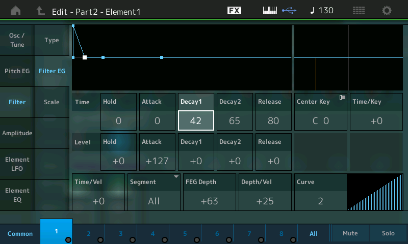
Changing the filter envelope of PART 2 (Element 1) in this example allows you to change the character of the modulation further. The short filter decay (Decay1Time) is especially important for the conciseness for the shape of the modulated Pad sound. If you increase the Decay Time, the intensity rhythmic modulation will be reduced more and more.
The Envelope Follower’s impact can be easily demonstrated in this example by navigating to the Filter EG:
Go to the main PERFORMANCE (Home) screen.
Press [EDIT].
Press [PART SELECT 2/2] to view PART 2 parameters.
Touch “1” on the bottom line of the screen to view Element 1 settings.
Touch “Filter”.
Touch “Filter EG”.
Highlight the TIME parameter “Decay1” in the screen (shown):
Increase the value above 42, then decrease it again to hear what the Envelope Follower is doing as it shapes the overall sound.
The Amplitude Envelope Generator of PART 2 (Element 1) also gives you an opportunity to change the character of the sound. Both the Filter EG and Amplitude EG influence the sound output over time. Filter EG often depends on the Amplitude EG, because if the AEG does not allow for sound to happen, movement in the filter is meaningless. Therefore, if the AEG is not allowing any sound to occur, you will not be able to tell what the Filter is doing – they work together! In other words, the AEG allows for volume change. If there is no volume allowed, you will not be able to hear filter movement – simple as that. Of course, the sound and/or device you choose to generate the source signal will have a great deal of influence of the result.
Extra Credit
VOLUME (amplitude) is a very typical use for the Envelope Follower – and probably the best way to understand how it works – because we are using the loudness of a source to control the loudness of the target, but do not limit your thinking to the obvious or typical. Be sure to use your imagination and don’t be afraid to ask, “I wonder what will happen if …” This is part of the joy of synthesis!
For example, try Element Pan instead of VOLUME as a destination for the Envelope Follower. Now, instead of changing the volume of the target, you can have that audio burst create a movement in position in the mix – so get out your headphones as you send sounds swirling off into the atmosphere!
Things do not all have to happen in a typical pulsating rhythmic way, either; you can create your own custom control motions over entire sections of music. You can offset the timing or extend when and where and how things occur. We can only open the door and let you peek down the long hallway – it is for you to explore and create the music.
Catch up on the previous article in the series – “Mastering MONTAGE 10: Side Chain Modulation” here.
The next article in this series – “Mastering MONTAGE 12: Motion Sequence” is available here.
In this lesson, we’ll explore the “Side Chain” function of the MONTAGEMotion Control Synthesis Engine, which allows for modifying one Part with another. It also extends to the external world as well, because the source Part could be an external input (microphone, guitar, audio device, etc.). This can take several forms; we’ll take a brief look at three of the basic possibilities – including one popular in Electronic Dance Music.
(NOTE: The Live Set used in these tutorials can be downloaded here.)
Side Chain Modulation
PERFORMANCE 11: Side Chain Comp PERFORMANCE 12: Side Chain Arp PERFORMANCE 13: Side Chain RingMod
The following Insert Effect Types have a Side Chain Input Routing option when a source (called the “Side Chain Part”) is selected for the Insert Effect in the Part Effect window:
VCM Compressor 376
Classic Compressor
Multiband Compressor
Ring Modulator
Dynamic Ring Modulator
Dynamic Filter
Dynamic Phaser
Dynamic Flanger
Insert Effects are those that are unique to the instrument sound occupying the PART. Each of the MONTAGE’s 16 synth PARTs – plus the A/D input PART – has its own pair of Insert Effects, which are customizable on a per PERFORMANCE basis. These can be configured in series or in parallel and can be routed to from within the synth engine. Significantly, the Insert Effect is not shared by any other PART, and is routed “inline” with the particular instrument sound, allowing you to control this Effect on a per PART basis with assigned physical controllers.
Note: Side Chain Modulation is immediately active upon selecting a Side Chain Part for the respective Insert Effect, even if the Side Chain Input Level is set to zero. The zero level is an offset value, which can be increased or decreased for controlling the depth of the Side Chain Modulation.
Note also: To avoid unintended Side Chain Modulation, the Side Chain Part selections for Insert Effects should be left in the default condition – that is, set to OFF. A Part selection should be made only for activating Side Chain Modulation. To understand this, the SIDE CHAIN connection option allows audio signal from the source PART to enter and influence (that is, modify) the output of the current PART via its assigned INSERT EFFECT. So just by making the connection, audio is routed in – what we can do is increase or decrease that audio. If you do not want audio signal to route via the side chain, simply leave the parameter set to OFF.
The PART with the INSERT EFFECT Side Chain Input will be modified by the PART you route via this “side” input.
The source signal becomes the modulation energy. Its audio creates the nature of modulation – the shape of the energy that is used to make changes in the target destination parameter. In the case of a compressor, you can have the audio pulse of one Part influencing the target destination’s audio. The Ring Modulator Side Chain can be used to add radical detuning on cue from the pulse of the audio source; the Dynamic Filter, Dynamic Phaser and Dynamic Flanger each add a distinct audio result in response to the selected source. These are just some very basic concepts to get you started; like patching in a modular synth, the actual results will really depend on your creative imagination – what you choose as the source and what you choose as the sound being modulated. In this lesson, we’ll show some typical examples, but these are what’s already been done (and is now popular) – experimentation is required here for optimum (or most unique) results. The best way to understand this is to hear it, then explore the settings.
PERFORMANCE 11: Side Chain Comp
This example shows a very typical Side Chain Compression result, where a “pumping sound” is created for a synth pad caused by the input of a bass drum groove. The Pad sound is interrupted by the input of the bass drum. PART 1 contains the Pad sound and PART 2 contains the arpeggiated Kick Drum. The Kick drum causes the Pad to “duck” in volume. So the Compressor is applied to the Pad in PART 1, and instead of using the Compressor to respond to the attack and release of the Pad itself, we are using PART 2’s audio to ‘duck’ the Pad via a Side Chain input:
In PART 1’s Compressor you would set PART 2 as the input (Side Chain Input). Side Chain uses the compressor’s Gain Reduction function to create an envelope. The Kick and the Pad cannot happen at the same time when fully applied.
Only two settings are needed for programming the Side Chain Compression of PART 1:
First, the Side Chain Part must be selected as Insert Effect “A” in the Part Effect window. It is PART 2, in this example, that includes the bass drum groove.
The Side Chain Input and its Level parameter are found in the MONTAGE by navigating to the PART’s Insertion Effect.
From the main PERFORMANCE (HOME) screen:
Press [EDIT].
Press [PART SELECT 1/1] to select and view PART 1 (Pad).
Touch “COMMON” in the lower left of the screen, if not already highlighted.
Touch “EFFECT” in the left column of the screen.
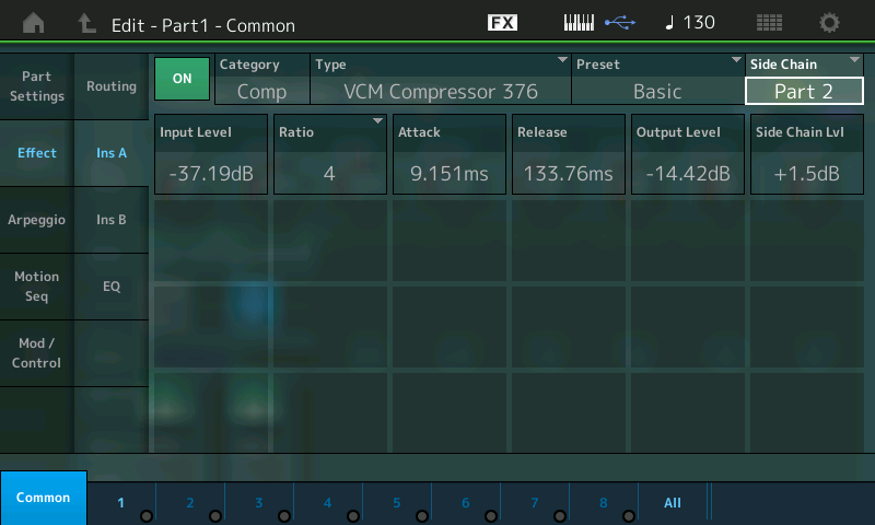
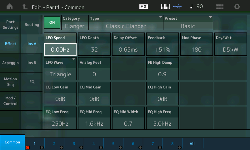
Touch “INS A” in the second column:
The Side Chain Input source selection and the Side Chain Lvl are found on the right side of the screen.
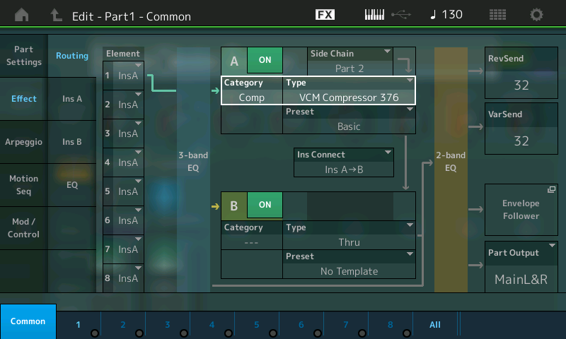
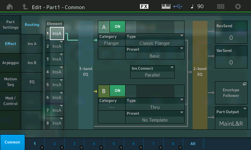
In the view of the overall Effect ROUTING, you can see where the SIDE CHAIN function is attached to the INSERTION EFFECT “A” box:
In this “Routing” screen you can see that each Element can be routed through one or the other (or neither) of the two Insert blocks (A or B). Currently, only Element 1 is active, and it is routed to the VCM COMPRESSOR 376. Notice that it passes through a 3-Band EQ pre the Insert Effects block, and there is a 2-Band EQ post the Insert Effects blocks.
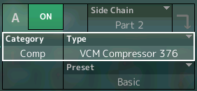
You can also see that the “INS CONNCT” option in the center can configure the Inserts in series (A>B, B>A), or in parallel. The “Side Chain” option appears above the Effect block where you select the Insert Effect TYPE (Insert A). You can reassign it easily here – convenient redundancy – so you can quickly and easily try out different modulation sources.
If you select one of the eight Insert Effect TYPES that support the Side Chain Modulation function, the Side Chain option box will appear. Notice the INSERT “B” (not used in this particular PART) has an empty space where the Side Chain function would appear. Nothing is there because one of the eight TYPEs is not selected. (The option only appears when the context is proper.)
Background Details: The SIDE CHAIN is a routing situation that allows audio signal from the SOURCE PART – in this case, PART 2 (an arpeggiated Kick Drum) – to create a modifying signal. Here, the amplitude “shape” of the Kick Drum audio will cause the compressor to engage. Compressors are a type of amplifier where the more signal you send in, the less you get out. It literally compresses the dynamic range (the difference between the softest and loudest sounds it receives).
The MONTAGE Compressor reduces the GAIN of the signal it is applied to – however, in SIDE CHAINING, we flip the script so that, instead of compressing the Pad, we are going to create an envelope from that incoming signal (the Kick drum) and use it to “duck” the Pad sound in PART 1. As the incoming signal rises in amplitude (in other words, as it attacks), it will cause the PART 1 sound to decrease (turn down) and as the Kick’s audio signal (energy) disappears, the PART 1 sound will return. The end result? A rhythmic pulsing/pumping sound.
“Ducking” is used often on the radio, where the DJ’s voice (source) causes the music to duck down while he/she is talking, and then automatically return to full volume after the DJ finishes speaking. You can control the ATTACK (how quickly it engages) and RELEASE (how quickly/slowly it lets go) of the signal creating the ducking action. The Attack Time and Release Time settings are critical to shape the results. When used for speech or singing, the Release should obviously be less abrupt than it would be on a percussive signal like a kick drum or snare drum. Basically, set them by ear!
This particular effect is also extremely popular in Electronic Dance Music, but exactly how you choose to use it will be a matter of experimentation and preference. Side Chain Compression is one of the most popular uses for Side Chaining. In MONTAGE, however, the options for this function are expanded – and the possibilities are many.
The Side Chain Input Level must be adjusted for Insert Effect “A”. Each SOURCE is likely to need specific adjustment, depending on exactly what you are using to create the reaction. A pre-recorded source is likely to be consistent and therefore easier to deal with, but virtually anything can be used as a source. Experiment!
The depth (application) of the Side Chain Modulation can be controlled with the Super Knob too, which in this case is assigned to the Side Chain Input Level (InsA SChnLvl). In this manner you can use the Pad normally and then morph to a situation where the Pad and Kick are interacting at the extreme.
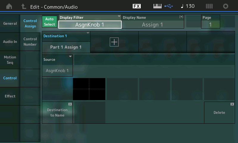
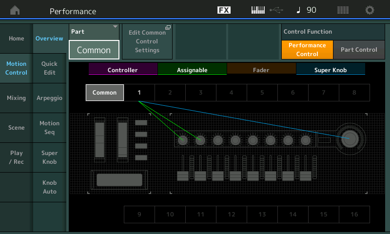
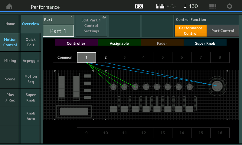
Here you can see the required settings in the Common and Part Controller Boxes, using these SHORTCUTS:
From HOME (touch the HOME icon upper left corner).
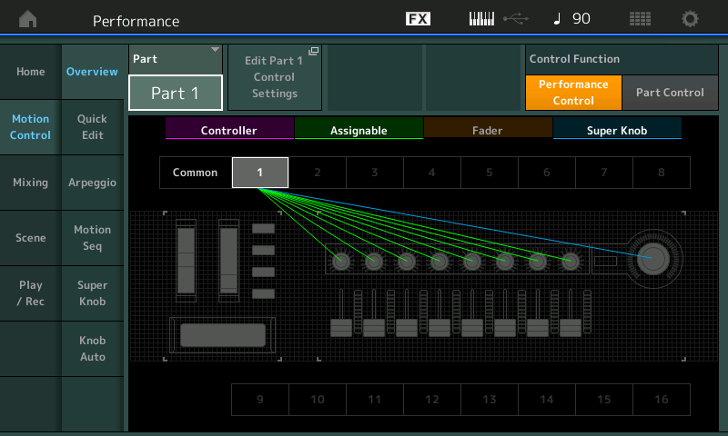
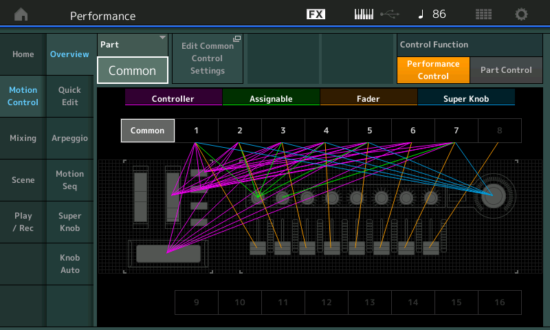
Press [SHIFT] + [PERFORMANCE (HOME)] to jump to the OVERVIEW screen.
With the PART = COMMON touch “Edit COMMON Control Settings”.
Make sure AUTO SELECT is green, then move Assignable Knob 1:
The start position of the Super Knob is center (64). Moving it to the right increases the depth, while moving it to the left reduces the side chain compression. Moving it to the left-most position cancels the modulation completely.
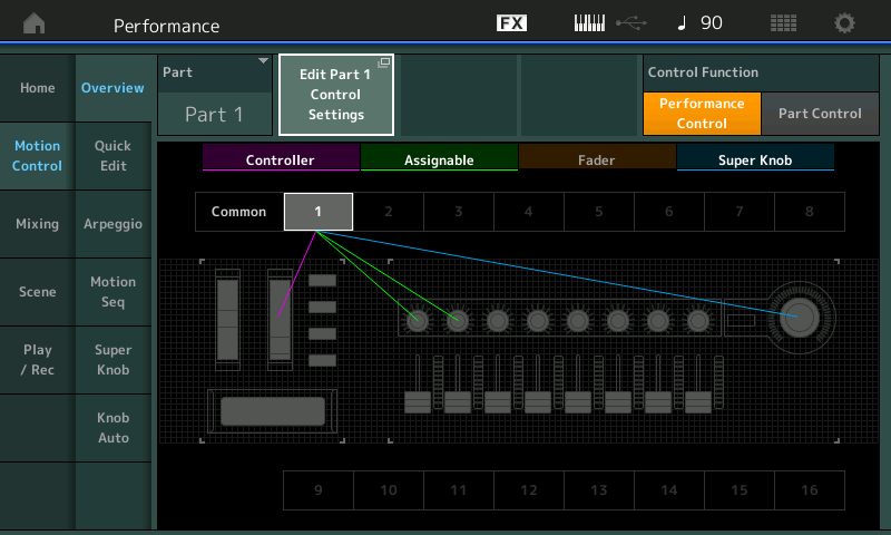
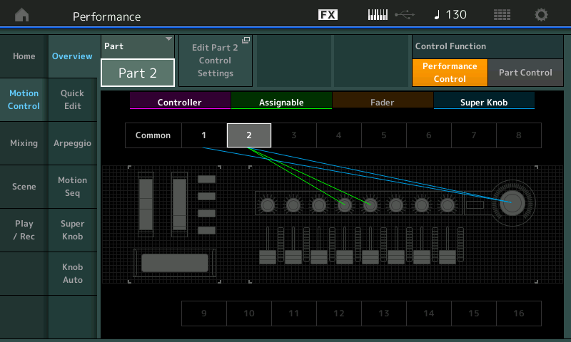
You can return to the OVERVIEW screen by pressing [EXIT] or using the [SHIFT] + [PERFORMANCE (HOME)], then change the PART = PART 1 and touch “Edit PART 1 Control Settings”:
EXTRA CREDIT
Call up factory Preset PERFORMANCE “Mr. Side Chain”.
Play a nice big full chord, hold it with the sustain pedal, and then recall SCENE #3.
Slowly rotate the Super Knob from 0 towards 127.
You will hear the KICK appear as you reach the 12 o’clock position, and as you increase from there, you will hear the Side Chain Compression Kick “ducking” the Pad sound.
Explore further: The MW will control the volume of PAD sound in reverse. In this PERFORMANCE, the kick drum in PART 7 is used as the Side Chain input to influence the big synth pad in PART 1. At the same time, PART 1’s Output is used as a Side Chain compressor input to influence the Arpeggiated PARTs 2 and 3. Play with this multi-dimensional interaction.
PERFORMANCE 12: Side Chain Arp
This example is a variation of the previous Performance = Side Chain Comp. But this time, instead of the arpeggiated bass drum groove in PART 2, a synth arpeggio part is used for the Side Chain Compression. The audio pulses caused by the arpeggio phrase now become the modifier. You can use the ARPEGGIO Play FX to create Swing, change the Gate (duration), or offset the Velocity – even change how the phrase references the clock (tempo).
PART 1 uses a soft string pad Waveform, which works in combination with the synth Arp of PART 2. In this example, the synth arpeggio plays a dual role, musically complementing the chords played and rhythmically interacting with the pad sound underneath.
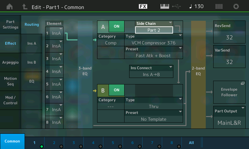
Below we see PART 1 – Common > “Effect” > “Routing” where the Side Chain input arrives from PART 2. Notice in the lower left corner you can see the PART OUTPUT, which is sent to the MAIN L&R outputs:
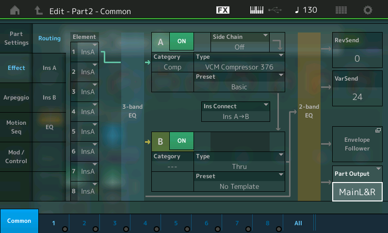
In the screenshot below, we see PART 2 – Common > “Effect” > “Routing” but the cursor is showing the PART OUTPUT. Experiment by turning the PART OUTPUT from “MAIN L&R” to “OFF”. You will still hear the influence of the Arpeggiated PART 2, but now you will not hear the sound of the PART directly. We point this out because it can be a very useful tool, and greatly expands how you “look” at arpeggios. You can use the rhythmic shape they create without using the musical note pattern that we typically always hear/expect from arpeggios. Remember, most anything can be a modifier in the Motion Control Synthesis Engine.
PERFORMANCE 13: Side Chain Ring Mod
This example is another variation, using the same modulation source (PART 2 with synth arp), but a different Insert Effect in PART 1. Different from the complementary functionality of the previous example, this time PART 1 supports the arpeggio groove, which is used as the modulation source.
Extra Credit
We will mention the VOCODER here simply because it is another INSERT EFFECT that allows for Modulation. While technically speaking, not a SIDE CHAIN in the same manner as the ones described above, one Part’s signal is fed into another via the target’s INSERTION EFFECT:
Load the PERFORMANCE “Chilled Vocoder” found in the PAD/CHOIR Category.
Here a Drum groove (Arp) in PART 2 is used to modify the synth Vocoder Pad sound in PART 1.
The Drum groove “speaks” through the Vocoder – and a slowly evolving Sound Effect (Rainmaker) in PART 6 is modifying a string sound (PWM Strings) in PART 5 via a second Vocoder assigned to Part 5.
Turn the Super Knob to the right from center to add more “vocoded” effect.
Press [EDIT].
Use the PART MUTE buttons (right front panel) to isolate just PARTS 1 and 2.
The direct out of the Drum Groove is assigned to OFF, so that you only hear the drums encoded onto the Pad sound in PART 1.
Use the PART MUTE buttons to isolate just PARTS 5 and 6.
The direct out of the Rainmaker sound effect is assigned to OFF, so you only hear its output encoded onto the string (PWM Strings) in PART 5.
Again, the source could be a drummer (“live” or via machine), a guitar player, a vocalist, a mix tape, your favorite playback device, another synthesizer – the sky’s the limit.
Catch up on the previous article in the series – “Mastering MONTAGE 9: Controller Box Switches” here.
The next article in this series – “Mastering MONTAGE 11: Envelope Follower” – can be found here.
Creating arpeggios for general use is an art. This two-part article will prepare you for making your own arpeggio data with the Yamaha MONTAGE. Knowing the rules will allow you to bend them – fighting the rules only leads to frustration. With that in mind, let’s begin with Part I of Arpeggio Making 101.
The Phrase Factory Factor
“In addition to its fresh and globally infused sound set, the Motif introduced keyboard players to arpeggiator patterns that added realism and musical interest to sequences and live performances. “Arpeggiator” is an understatement, as the word makes us think of robotic up-and down synth patterns. By contrast, even the original Motif offered tons of musical phrases suitable for its myriad instrument sounds, and made it fairly straightforward to drop those phrases into a sequence or Performance setup – or to go in the other direction, recording your own phrases in the sequencer, then triggering them from the keys as arpeggiator patterns. Yamaha called this approach “Phrase Factory,” and it gave the Motif an edge over workstations whose sequencers worked in linear, tape machine fashion. It also offered a degree of instant inspiration that won favor among many musicians.” – Keyboard Magazine (“A Decade of Motif”)
MONTAGE is able to load Arpeggio data (.X3G) made for the Motif XF directly to its internal USER Arpeggio bank. Creating your own arpeggios on MONTAGE (a feature that was added with firmware 1.20) is accomplished by using data that you record (or load) to the internal recorder as MIDI data. Once in the internal recorder, it can be converted into a User arpeggio. In general, you will be able to convert the data into one of three different general Types:
Arpeggios for musical instrument Parts (note/chord intelligent).
Arpeggios for Drum/Percussion Kit Parts (fixed note).
What is often difficult to understand about arpeggio creation is:
Not all data that you can play makes for a good arpeggio – and not all data can be made into a good arpeggio. The rules for creating them require that you understand the purpose of the arpeggio and also requires that you create data which lends itself to that purpose. Since an arpeggio is interactive, it differs from data that simply plays back.
The rules are simple enough: A maximum of 16 different (unique) MIDI note numbers can occupy an arpeggio phrase. The Convert Type will dictate the behavior of the arpeggio phrase. Because arpeggios can adjust notes in the phrase dynamically in response to keys you are fingering, there have to be specific rules/requirements restricting the number of unique note numbers, as follows:
Those arpeggios intended for musical instrument Parts will adjust according to the notes triggering them (chord intelligence).
Those arpeggios intended for Drum Kits (fixed note) will play back exactly the same every time with no adjustment, according to the note or notes used to trigger them (no chord intelligence).
Those arpeggios that are Controller data (which are not notes at all) are MIDI data that is applied to the Direct sound output made by the triggered notes – so instead of notes, you hear these controllers applied to the direct sound. For example, if the Controller is Pitch Bend, the chords that you hold will be bent by the arp phrase data, so without a “direct” sound to which the data is applied, there is no sound generated by Controller data.
Basic definitions
Arpeggio Phrases are most often Note data, but may also be Controller movements that can be triggered by the keyboard to play in looping or one-shot fashion. They reference the MONTAGE clock tempo, and can play at multiples or sub-divisions of that tempo. They can Swing, and can be adjusted as to timing and duration, where applicable. Controller Arps require that the KEY MODE be set to one that allows “direct” notes to be triggered, so that the Controller movement can be applied to the sound. (i.e., “Direct”, “Sort+Direct”, “Thru+Direct”).
An arpeggio phrase is somewhat different from a typical sequencer phrase, specifically in the way in which you get it to play back. When you record notes to a sequencer you simply press the Play button and the notes that you recorded are played back. In contrast, an arpeggio’s ON button does not cause the notes to “play back.” Instead, you must also press a key, or arrangement of keys, within a specific range on the keyboard in order to trigger the start of playback; those conditions must exist for you to have the arpeggio play. It does not simply start when you turn the ARP ON/OFF button ON or you simply press a button – it requires being armed as well as real time input via the keybed of the MONTAGE. That input can be simply to start it and/or to tell it what pitches to access if the arp is ‘chord intelligent.’ It’s ‘alive’ in that it can respond to change. A sequence just plays back as recorded. Arpeggios can react.
Later we’ll learn that you can even control dynamics (i.e., how loud or soft) the arp phrase plays. An arp phrase can continue automatically, or be set to play only when you are engaging the keys. It can reset to the top and begin again, or be set to continue running in silence when you lift you hands from the keys. You can also re-engage the phrase in place when you press the keys:
The Arps created for musical instrument Parts will respond according to what you voice on the keyboard – they will change what they play by recognizing chord qualities such as Major, Minor, Dominant, Diminished, and Augmented chords.
The Arps intended for Drum/Percussion Kits (generated by a Convert Type called “Fixed Note”) generally do not change – you simply control when the phrase starts and whether the phrase continues.
Controller Arps contain non-note events that influence the sound that you are playing. For example, a ‘pitch bend’ arp would result in the sound you are playing varying pitch, as opposed to a dancing pattern of notes.
Convert Types
There are three Convert Types: Original Note, Fixed Note, and Normal. Before you can begin making your own arpeggio phrases, it will be important know what these Convert Types do, as well as the way the USER ARP creation feature uses its four tracks to create a single arp phrase.
Normal: The Arpeggio is played back using only the played (fingered) notes and its octave notes. Fixed: Playing any note(s) will trigger the same MIDI sequence of data. Org Notes (original notes): Basically same as “Fixed” with the exception that the Arpeggio playback notes differ according to the played chord or key.
The following experiment will help you clearly hear/understand the differences in these Convert Types. We will begin by setting up the MONTAGE to operate in sixteen-part multi-timbal mode and then record a musical phrase, convert it into arpeggio data, and observe how the different Convert Types do their thing:
Lesson 1: How Arp Convert Types deal with Note data – Phrases
From the PERFORMANCE (Home) screen:
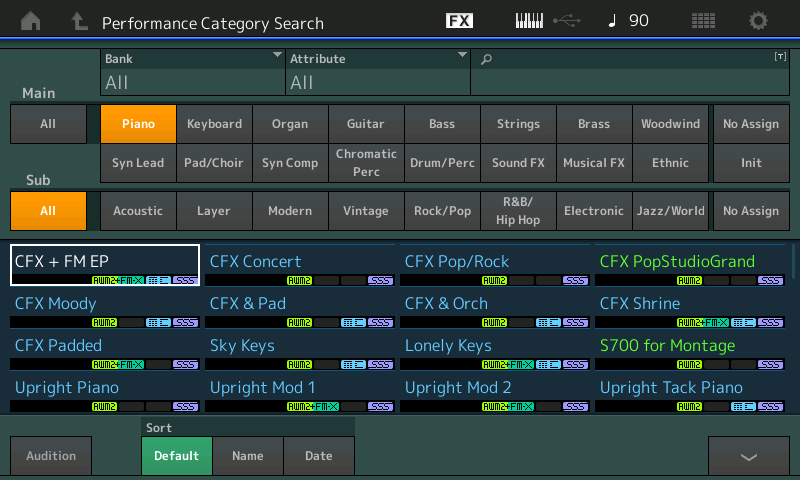
Press [CATEGORY SEARCH].
Select “Init” > “Multi/GM” and return to the Home screen.
Press the PLAY button to go to the PLAY/REC screen.
Set a comfortable TEMPO.
Record the first four measures of the song “Mary Had a Little Lamb” in the key of “C,” starting on the “E” above middle “C.”
What? Why? Well, it’s public domain and we all know it – and it’s what happens to it that will make the Convert Types completely clear. And you will get it right away:
Mary had a little lamb, little lamb, little lamb,
Mary had a little lamb,
Its fleece was white as snow.
If you create three Arps, one from each Convert Type, using this recording, your understanding of Arp Types will take a major step forward (pun intended). That’s because you will learn what to expect and you will immediately be able to hear/understand why the results are what they are.
So now:
Use the “ORG NOTE” Convert Type for the first experiment – Create ARP 1.
Use “FIXED NOTE” next for our second experiment – Create ARP 2.
Use “NORMAL” Convert Type for our third experiment – Create ARP 3.
When you complete the recording of the phrase:
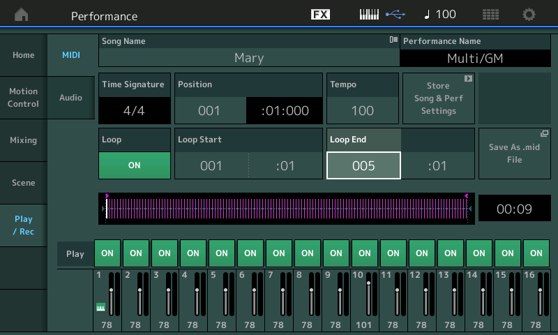
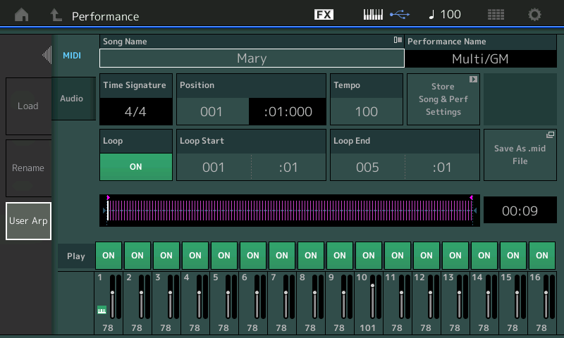
Verify your work by setting LOOP = ON and set the Measure region you wish to Convert (make sure it can loop properly).
As shown in the screenshot below, I recorded at a tempo of 100 BPM and set the Loop Start at Measure:001/Beat:01 and the Loop End at Measure:005/Beat:01 so as to capture four complete measures:
Touch the screen area where the NAME appears.
A pop-in will appear and allow you to convert data to create “User ARP”:
Touch “USER ARP”.
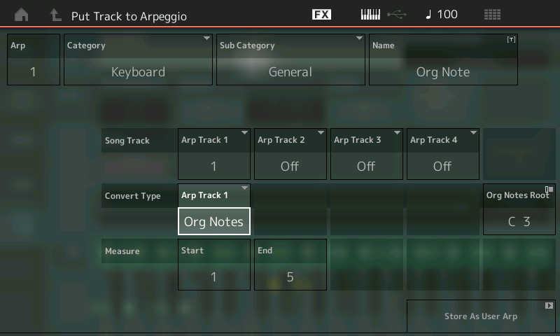
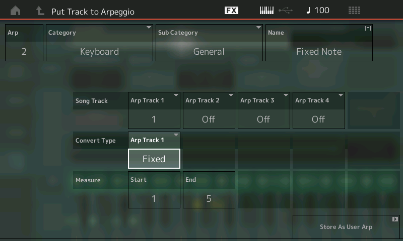
A “Put Track to Arpeggio”dialog box appears:
In the dialog, set the target USER location (upper left) for the ARPEGGIO to start with ARP “1”.
You can also set a Category and Sub Category for the Arp data (this will help you find it later).
You can also NAME the ARP – call it “ORG NOTE” (very important in finding it later). We’ll call it this because you are going to discard these – this is just for learning purposes.
Set the Measure range:
Start = 1
End = 5
Which is: top of measure 1 through to the top of measure 5 (or 4 complete measures).
For “ARP TRACK 1,” set the SONG Track you used to record the phrase (we used Song Track 1) and set the “Convert Type” to ORG NOTES. (There are four Arp Tracks – we will cover the use for these other tracks in a later article, for now just use the first ARP Track Convert box.)
When you set the Convert Type = Org Notes, the “Original Notes Root” parameter appears. Cursor over and set the Org Notes Root = “C3”. This setting sets the Key. Now, when we touch “C3” the phrase will play back at its original pitches.
Touch “Store as User Arp” to execute (lower right corner of the screen). You have now created USER Arpeggio 1 that will be chord intelligent with the ability to recognize the lowest pitch as the ROOT – and it will play correctly when fed the correct chord quality.
Now that you have created your melodic phrase and converted to an ORG NOTE Arpeggio – it can be assigned for use by any PART in any PERFORMANCE. You do so by editing the PART’s COMMON parameters.
Go to the “HOME” screen and try it out by assigning it to PERFORMANCE PART 1:
Press [EDIT].
Press [PART SELECT 1].
Touch “COMMON” lower left corner of the screen or press the dedicated lower [COMMON] button on the right front panel.
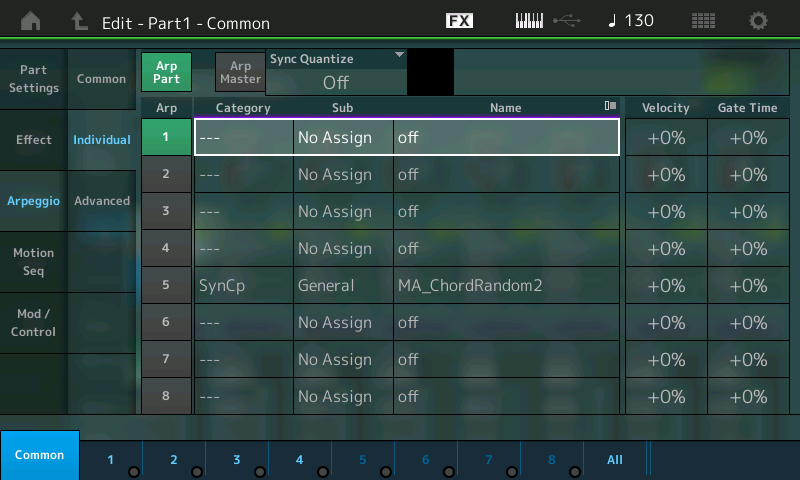
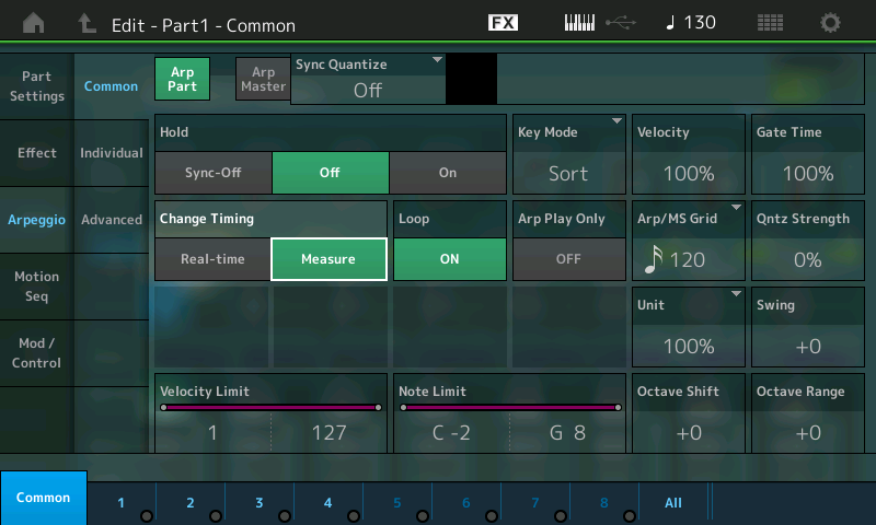
Touch “Arpeggio” > “Individual”. Here is where you can select as many as eight Arp phrases for this PART:
Touch slot number 1 Name area (shown highlighted above) to see the pop-in menu.
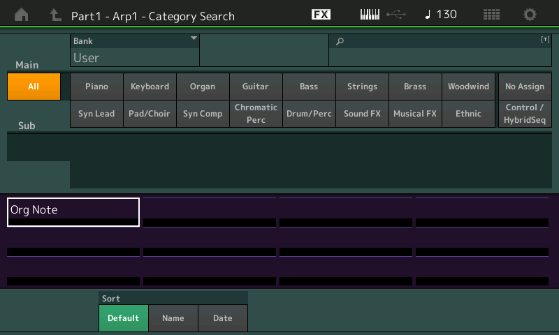
Touch “SEARCH” > set the search option BANK to “USER” and the Main Category to “ALL”.
Assign your “USER” ARP to this PART:
Find “Org Note” > and highlight it > [ENTER] to make the assignment.
In the second column are two other pages of parameters: “Common” and “Advanced”:
Touch “Common”.
Here you can set the overall settings for the ARPs for this PART.
Set “ARP PART” SWITCH = ON (green).
Set HOLD = ON or OFF as you desire (SYNC-OFF is a special case that keeps the timing of the arpeggio running in the background even when you are not triggering the keys):
Activate the “ARP MASTER” switch (green) – you can also press the dedicated ARP ON/OFF master switch located above the MW on the left front panel.
On this screen are also the Key Mode and Play Effects, as well as the Velocity Limit and Note Limit regions that define how these arpeggios will be controlled. In Part IIof this article, we’ll dig deeper into these settings and the “Advanced” settings. For now, just go with the defaults.
Hearing what the ARP Type does
Try the following, one-by-one, and observe the results:
If you play and hold just a “C” it will play the melody in the key of C.
If you play just a “D” it will transpose the melody to the key of D.
If you play a C minor chord it will play the melody with a Flat 3rd. (If you play just “C-Eb” that is enough to define the C minor chord.)
If you play a D minor chord it will play the melody in D with a Flat 3rd.
If you play a C diminished chord it will play the melody with a Flat 3rd and Flat 5th – etc. etc.
It is that simple… and that complex!
Now try the different HOLD settings: On, Off, Sync-off. Rinse and repeat the Convert experiment, this time assigning the “Convert Type” to “FIXED”. Here’s how:
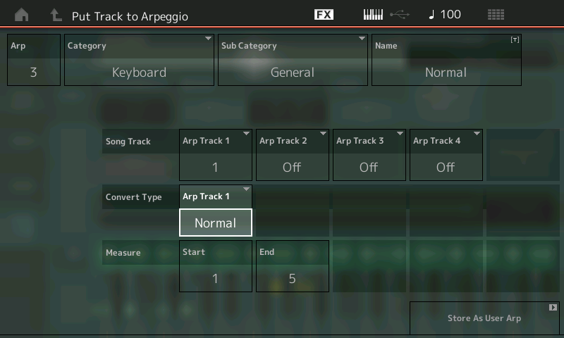
Go back to your PLAY/REC screen (press the PLAY button) and setup to create another “User Arp” from the same data by touching the SONG NAME box – and touching the “User Arp” option:
With the same melody source (Arp Track 1) – this time using the “FIXED” type – notice the target in the dialog box automatically increments to ARP “2” (upper left corner). Name this second ARP “Fixed Note”. “FIXED” is similar to “ORG NOTE” in that it can play a specific melody, except: no matter what key you use to trigger playback the result is “fixed” – it does not transpose. This convert type is ideal, as you might imagine, for DRUM and PERCUSSION arps. (Drummers do not transpose nor adjust notes to the key you are playing in). The fact that “fixed” plays exactly what you play can be used in any way you see fit – but remember the sixteen unique note number rule.
Go to the HOME screen and assign User Arp 2 so you can apply and hear it.
Finally:
With the same source song melody, use the Convert Type “Normal”. This is what a traditional arpeggiator normally does – it plays the rhythm of your source data and takes the information of the currently held notes to do its thing with it. It will probably never play the melody correctly on its own:
Remember: Arps traditionally did not do melodies. Instead, this (what you find in the Motif/MOXF and MONTAGE) is a re-invention of the traditional arpeggiator. Arpeggios traditionally did up, down, up/down, down/up, and random, etc. Later they were capable of producing more complex rhythmic effects; eventually you could create phrase-based melody arps, counter-melody arps, and the kind of guitar intelligent chord voicing arps that you find in the XS/XF/MOXF/MONTAGE.
It should be clear now what the CONVERT TYPES are designed to do. With this knowledge you can start to apply the tools for creating your own arpeggios. In Part II, we’ll take a close look at some of the more detailed arpeggios, and the way they were made – for example, those used for strumming guitars, etc.
There are some 256 User Arpeggio locations. You discard unwanted arps by overwriting them, or you can manage them in UTILITY mode. They will be stored in their own internal FOLDER. Go to [UTILITY] > “Contents” > “Data Utility” > find the “ARP” Folder – this contains your USER ARPS. Access the “JOB” function to select/deselect ARPs.
Recording Drum Arps
As you know by now, the Fixed Note “Convert Type” is designed to play back the exact keys you have fed in. While this is ideal for drums, it also means you can use an Arp Phrase to play an exact music phrase. How you use the feature is up to you. Do remember the rule: 16 unique note numbers. This means your Drum Kit selection is limited to a 16-piece drum kit. You can hit each drum over and over again, but you are limited to 16 different drum instruments.
You can create drum tracks using the onboard recorder or an external DAW like Cubase. Create your drums by your favorite means (Groove Agent is a powerful Cubase plugin tool for creating drum pattern data), then export your creation as MIDI data and convert it into MONTAGE Arpeggio phrases using the User Arp convert feature.
In Part II, we’ll take a look at how the different Convert Types deal with Chord phrases. Ready to start? Click here.
In this lesson, we’ll learn how to use the MONTAGEController Box Switches.
(NOTE: The Live Set used in these tutorials can be downloaded here.)
PERFORMANCE 10: ControllerBoxSwitchA
Sometimes you need to make control assignments only to specific Elements within the AWM2 PART (or to specific Operators within the FM-X PART). In the default setting, the control assignments are valid for all Elements of a Performance. The individual assignments for Elements can be done on the Controller Set screen – you can select the Element for Destinations that allow individual selection.
This means that all used control settings made in the Part Controller Set are initially enabled. If you select a parameter that allows for individual Element assignment, you must OPT OUT for the individual Element. The default is that an ELEMENT is set to OPT IN. In other words, if you select a parameter Destination that does offer individual ELEMENT assignment, the Elements are initially set to active (ON) by default. If you don’t want to control an Element, turn its individual Switch OFF. Of course, if you do not select the parameter Destination, its being ON or OFF is of no consequence, because you will not be changing anything.
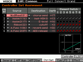
For better understanding, it may help to compare this function with the corresponding function in the Motif XF – the “Element Switch” in the Controller Set Assignment:
As you can see in the above screenshot, the Effect parameters are unchecked or greyed out because they cannot be used individually for Elements. This is because of the selected Destination. The entire sound (all Elements together) is routed through the selected destination (Effect). “InsA-HSH G” (Insert A – High frequency Shelving Gain), which is an EQ, and “Reverb send” are both situations where the entire program is processed and so it is not possible to select just a single Element.
In CONTROLLER SET 4 and 6 (Destinations “cutoff” and “AEG release”, respectively) the boxes are checked for all Elements. Here you have a choice, and all Elements are opting in.
In CONTROLLER SET 3 (Destination “Element Level”), the box is checked only for Element 8. The programmer would have had to uncheck Elements 1-7 in order to OPT OUT.
A CONTROL SET on the Motif XF consisted of a SOURCE (physical control) and a DESTINATION (target parameter). DEPTH dealt with the application of the controller – both range and direction – to appropriate Destinations, but only when you were provided the option to select specific Elements individually. Also, the Motif XF had only six Control Sets, while MONTAGE provides 16 Control Sets per PART, plus an additional 16 for the COMMON/Audio level of editing. There are also a host of new parameters like Curve Type and Polarity, as well as advanced shaping tools that let you customize the application of controllers.
These new shaping tools exponentially increase the DEPTH function that was available in the Motif and MOXF series because it no longer has to be linearly applied. In fact, MONTAGE allows you to completely customize the DEPTH shape, plus you can apply it manually or automate its application. This is at the core of the MONTAGE Motion Control Synthesis Engine.
The layout is a bit different, but the operation is fundamentally the same:
If a Performance Part doesn’t require individual Element assignments, you can keep the Controller Box Switch as it is – all Element Switches default to ON.
If you want to make individual Element assignments, you have to edit the Controller Box Switch matrix.
CONTROL ASSIGNMENTS are easy to deal with because they are seen within the PART’s Element/Operator view and are made intuitively as you think about them. It’s very much like patching a modular synth in that, as you build your sound, you make the necessary connections/assignments. The key thing here is that the Destination (parameter) determines whether or not the Element/Operator Switches appear or not. Obviously, some Destination parameters are PART destinations (i.e., they affect all Elements or Operators together, like common Volume, Send to Reverb and Variation, etc.) while others are individually switched per Element or Operator (like Element Level, Element Pan, AEG, FEG and PEG parameters, Cutoff, Resonance, LFO, etc.). This can be seen as equivalent to the kind of “patching” you would do in voltage controlled analog synthesizers if you had a wall unit full of modules. Think about all the individual envelopes you can control within the eight PARTS – each with as many as eight Elements (if AWM2) or eight Operators (if FM-X).
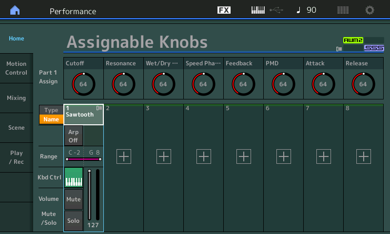
The “PERFORMANCE 10: ControllerBoxSwitchA” example includes a simple Super Knob morphing between two different organ Waveforms within a single Part:
Element 1 = Gospel.
Element 2 = 1st Four Draw.
Instead of the organ sound occupying a Part, here each organ sound is a single Element within the same Part.
Element 1 Gospel is assigned to the right (fully clockwise) position of the Super Knob. Element 2 1st Four Draw is set to the left position. In the center position you will hear an equal mix of both.
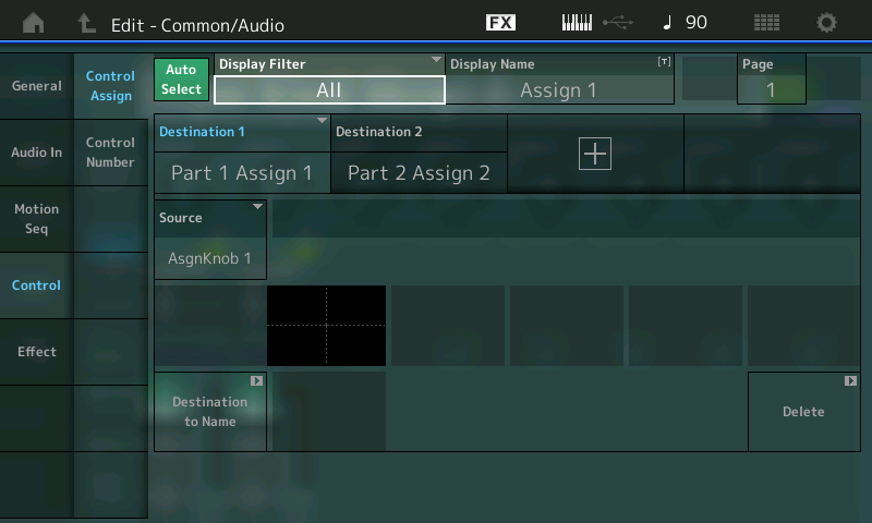
The first step is to make the Super Knob assignments in the “Common/Audio” Controller Box: The first two Knobs (Assign1 and Assign2) are set to link with PART 1 on this upper Common/Audio level (the Super Knob level). Instead of morphing between PARTS, we are now working within a single PART by manipulating individual Elements (since this is an AWM2 sample based program). Each Element references a Waveform. A Waveform organizes a set of samples mapped to respond across the keyboard at specific pitches and velocities.
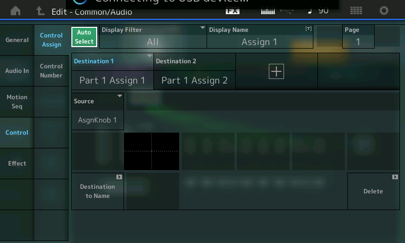
From the HOME screen:
Press [EDIT].
Press the upper [COMMON] button.
Select “Control” > ” Control Assign.
With the AUTO SELECT (green) active you can view the assignments either by moving the Knob itself or setting the DISPLAY FILTER = ALL:
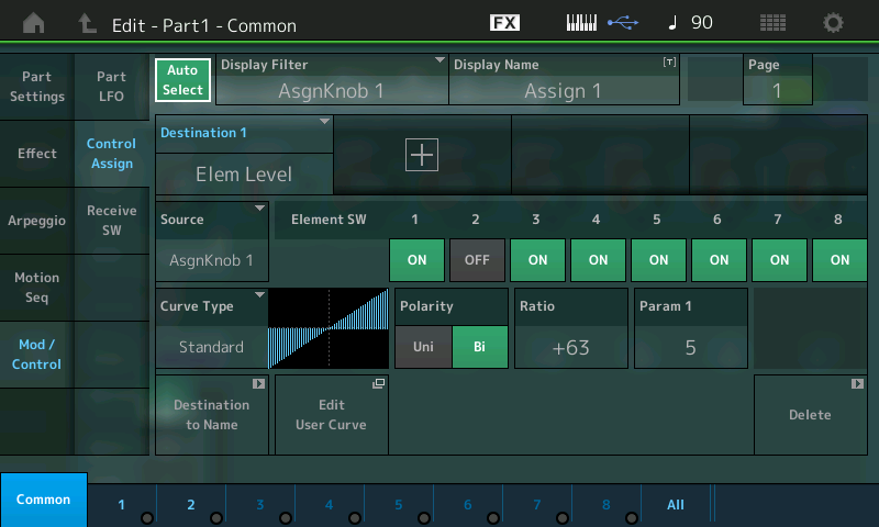
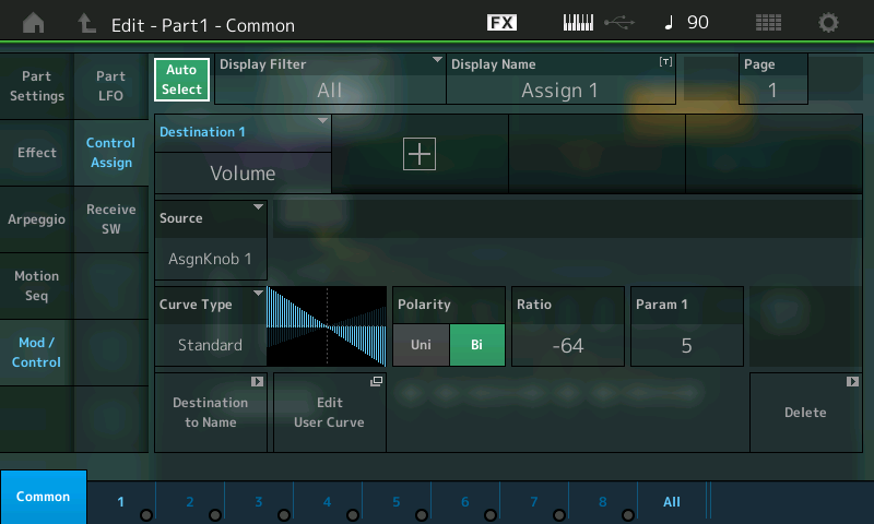
Next, follow the assignments in the Part Controller Box, which is basically the same as morphing between Parts, but this time using the Element Level as destination. Let’s take a look at the two PART 1 destinations:
Press the [PART SELECT 1/1] to view “Edit – Part1 – Common”.
Select “MOD/CONTROL” > “CONTROL ASSIGN”.
Ensure that “Auto Select” is active (green).
Move ASSIGN KNOB 1:
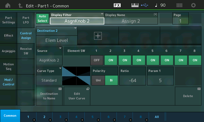
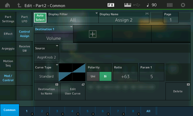
Then move ASSIGN KNOB 2:
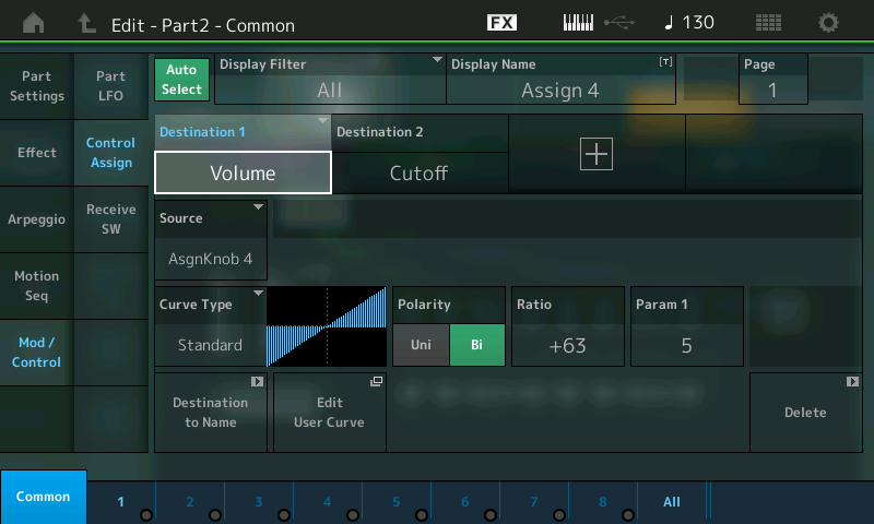
(Top screenshot) Assignable Knob 1 (Ratio +63) = Element Switch 1 ON, Element Switch 2 OFF.
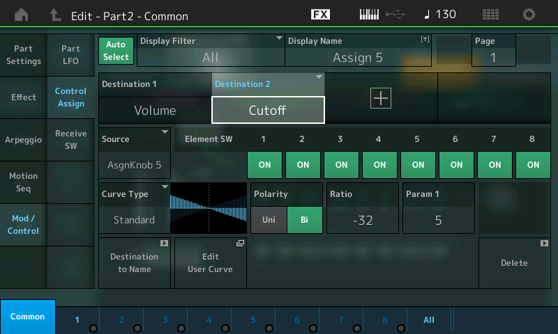
(Bottom screenshot) Assignable Knob 2 (Ratio -64) = Element Switch 2 ON, Element Switch 1 OFF.
It should be noted here that you can STORE the position of the Super Knob with the PERFORMANCE. So if you want this Performance to come up with the 1st Four Draw Element alone, you would store the Super Knob at a value of 0. If you wanted the Gospel Element alone, you would store the Super Knob at a value of 127. If you wanted to recall the sound with both Elements, you would store the Super Knob at 64 (for both at equal level), or any balance you desire.
From the PERFORMANCE (HOME) screen:
Touch “Motion Control” in the main screen’s left column.
Touch “Super Knob” in the second column.
SUPER KNOB value is in the lower right corner.
SOURCE: DESTINATION CONTROL ASSIGN Shortcut:
This is a good example of how easy it is to assign a parameter (Destination) to a controller (Source) with MONTAGE. Up until now on our “scuba tour,” we’ve been going through all the screens where this all takes place, but here’s a quick and easy assignment for you snorkelers. Say you’ve selected the Rotary Speaker TYPE as Insert Effect “A” and you want to assign Rotary Speaker: Speed Control to the MOD WHEEL. (Notice this Performance does not have it assigned).
Start from the HOME screen (touch the icon in the upper left corner):
Press [EDIT].
Press [PART SELECT 1/1] to view the PART 1 parameters.
Touch “COMMON” (blue) in the lower left corner or the screen.
Touch “EFFECT” in the left column.
Touch “INS A” to view the parameters of the Rotary Speaker.
Move the cursor to highlight Speed Control (shown):
Press the [CONTROL ASSIGN] button (located to the left of the screen below the Super Knob), which is now illuminated. The Destination Parameter will appear in the screen and it will tell you to activate (move) the controller you wish to assign:
Now move the Mod Wheel:
Done! This procedure takes you immediately to the Controller Assign screen, where you can tweak the Controller response (Depth) and/or Delete the assignment (Lower right corner of this Control Set screen). Notice that the Element Switches do not appear since they are unavailable – that’s because all Elements will be affected by the application of the Rotary Speaker Speed change.
In the OVERVIEW you can now see how the MW (Controller) is linked to PART 1 (magenta):
The [CONTROL ASSIGN] button, located to the lower left of the screen below the Super Knob, will glow whenever you move the cursor highlight to a potential assignable parameter. This allows you to rapidly assign, then scale and shape the application of that controller.
Catch up on the previous article in the series – “Mastering MONTAGE 8: Assignable Knobs” here.
Check out the next article in the series – “Mastering MONTAGE 10: Side Chain Modulation” here.
Here’s a lesson in how to leverage the power of MONTAGEusing the Part Assignable Knobs.
(NOTE: The Live Set used in these tutorials can be downloaded here.)
PERFORMANCE 9: Assignable Knobs
The previous examples in this series showed how to use the Assignable Knobs of the Performance Parts for building Super Knob assignments. However, independent of the Super Knob, you can use the Part Assignable Knobs for individual assignments after selecting the Part.
Important: You can control only one Part at the same time with Assignable Knobs (the currently selected/highlighted PART). But you can use the Super Knob and the Assignable Knobs of the selected Part at same time!
This example shows how Super Knob assignments can be combined with individual assignments to the Part Assignable Knobs (which are not routed to the Super Knob). Getting your head around this may take some time, but before there was a MONTAGE with a Super Knob, an Assignable Knob would be assigned to control a specific parameter within the current PART. This can still be done, and it remains unaffected by the movement of the Super Knob for this PART. Often a PART of your PERFORMANCE may be selected (highlighted) for individual direct play/control, while the others are responding to messages generated by the Arpeggiator. For example, you might have a two-Part split Performance with a lead sound in the right hand and a bass in the left, and you might want to have a knob that just affects the lead Part. In such a case you may opt to simply use an Assignable Knob independent of the Super Knob.
Each PART, when selected for direct play/control, has access to the three rows of eight Knob functions plus its own eight Assignable Knobs. In effect, you have 32 Knobs, plus the physical controllers (MW, PB Wheel, the two Assignable Switches, Ribbon, Aftertouch, FC1/FC2, Faders [Control Sliders]), the Motion Sequences, Arpeggios, the Envelope Follower, etc. – all of which can be called upon while the Part is selected. An extensive Receive Switch matrix allows you to determine which physical controllers are active per Part. Between the Super Knob – which can work independently – and the controls available to your currently highlighted (selected) Part, you can design almost any scenario.
This example Performance includes only one Part with a typical fat sawtooth synth pad. All eight Part Assignable Knobs are assigned to parameters within this PART, but only two of them (1 + 2) are also routed/linked to the Super Knob:
In the previous examples of the SUPER KNOB assignment, we saw how, on the Performance upper “COMMON/Audio” level, you needed to assign “Part 1 Assign 1”, “Part 1 Assign 2” and so on, to make each Knob accessible via the Super Knob. In this example, only these first two are using the Super Knob. The other six Knobs are individually accessible when you highlight/select the PART, as we’ll see below. (This is very similar to the Motif XS/XF Performance, where, when you selected an individual PART, the Assign 1 and 2 Control Knobs would address parameters for just that individual PART).
To view the Assignable Knob layout, go to the OVERVIEW screen – [SHIFT] + [PERFORMANCE (HOME)] – or from the main screen touch “MOTION CONTROL” > “OVERVIEW”
First, view the Performance COMMON Assignable Knob assignment:
Change the PART parameter from “COMMON” to “PART 1” to view the Assignable Knob layout for PART 1:
There is one DESTINATION parameter assignment for each of the PART’s eight Assignable Knobs.
To view the actual 8 Destination Control Settings, use the “Edit Part 1 Control Settings” shortcut – set the DISPLAY FILTER to “ALL”.
You can view Destination 1 ~ Destination 4 on the first Page. There are two PAGES.
PAGE 1:
PAGE 2:
The currently displayed “DESTINATION” has a number from 1-16. Touch that designation to view its data. Touch the parameter setting to view an overlay of possible parameter Destinations.
The Super Knob starts with the center position (64). This is useful for combining it with Part Assignable Knobs, which are set to center position by default. For this reason, selecting Bipolar (Polarity) for all assignments in the Part Controller Box is needed, since Bipolar allows you to move the parameter up or down, depending on whether a positive or negative value is set for RATIO. Positive values increase as the Knob is turned clockwise
The Assignable Knobs can be used for controlling the listed eight parameters: Cutoff, Resonance, Insert “A” Dry/Wet, Insert “A” LFO Speed, Insert “A” Feedback Level, Element LFO Pitch Modulation Depth (vibrato), AEG Attack, AEG Release.
At same time you can use the Super Knob, which controls the Assignable Knobs 1+2. But you should avoid using the Super Knob and the Assignable Knobs 1+2 at same time, because they are controlling the same parameter.
You can see the movements of the Super Knob at the LEDs of the Assignable Knob 1+2.
I’ve edited and stored this PERFORMANCE, renaming the individual Destinations for this PART (PART 1) (DISPLAY NAME). By default, they are simply named: Assign 1, Assign 2, Assign 3, Assign 4 and so on.
This DISPLAY NAME will appear on the main PERFORMANCE screen when PART 1 is the “selected” (highlighted) PART, as shown below:
They will read ASSIGN1, ASSIGN2, etc., when you are on the upper level of the PERFORMANCE (because they can be doing different things if you activate other PARTs), but if you select Part 1, the name you provide as the “Display Name” will appear. (Select the Part by pressing [PART SELECT 1/1] or by touching the TYPE/NAME box above PART1.) Now you will see that I’ve identified what each of them is doing to PART 1. Because you can SELECT only one PART at a time, it makes total sense to be able to read what that Knob is assigned to – this cuts down immensely on the guessing about what a Knob is doing!
It appears that many of the PRESETs simply have the word “Assigned” as the PART “Display Name” – which at least lets you know it is doing something. If it is not assigned, the Display name area appears blank.
Using the “Display Name”
From the upper COMMON/Audio level (or when the PERFORMANCE NAME is highlighted), the KNOBS will simply read ASSIGN 1 – ASSIGN 8. When you select an individual PART (either by touching the PART Name or by pressing [PART SELECT 1/1] ~ [PART SELECT 8/8]), you have the option of viewing the KNOB assignment by what it is doing. You can even give it a “nickname” – anything that you wish. This is extremely cool because you can be descriptive. The Presets only indicate which Knob is “Assigned” when you select an individual PART.
Imagine the PART Knob is controlling an FM Element that causes RING MODULATION when you raise its Modulation Index (Output Level). Saying it is “Output Level” is not as helpful as naming it “+RingMod”.
So selecting any single PART 2-8 (so that it is the highlighted PART) will show you what each of the knobs is assigned to control. This can be very useful and can make exploring Performances much easier because, when scuba diving, it can get quite deep!
Catch up on the previous article in the series – “Mastering MONTAGE 7: Super Knobs Values” here.
Next article – “Mastering MONTAGE 9: Controller Box Switches” – available here.
In this lesson, you’ll learn more about using the MONTAGESuper Knob in setting parameters and limitations for shaping your modulations.
(NOTE: The Live Set used in these tutorials can be downloaded here.)
PERFORMANCE 8: Super Knob Values
In the previous examples, the range and envelope of the modulations were set in the Part Control Box using the Curve, Polarity and Ratio parameters. Additionally, you can use another setting for shaping the modulation that is a bit more targeted. This is possible using the Super Knob Value 1 and Value 2 in the Super Knob window. These determine the limitations for modulation ranges by setting MINIMUMs and MAXIMUMs.
If you have programmed a wide range – or even the whole range – for controlling a specific parameter in the Part’s Controller Assign, you can limit this range using the Super Knob Values 1 and 2.
In the default setting you will find the Super Knob set to full range (0 – 127) for all knobs. The stored value here is Super Knob = 64.
Limiting the range via the Super Knob Values might be easier than trying to find the intended ranges using only the parameter of the Part Controller Box. If you make rough settings in the Part Controller Box first, you can do the fine adjustment of the range to be controlled in the Super Knob window with Value 1 and Value 2.
To be clear: It is not the range of the Super Knob itself that is limited with the Value settings. The Super Knob is still working through the complete range from leftmost to rightmost. Only the controlled parameter range of the target will get smaller.
You can use the example “Performance 0008 Super Knob Values” for checking the Value 1 + 2 function. It includes only one Part and one control set with the Destination LFO Speed of the chorus effect. This allows you to recognize the parameter changes very easily.
The settings in the Common/Audio and Part1 Controller Boxes are very simple and basically no different from previous examples:
The CURVE is Standard; POLARITY is Bi; and the RATIO is set to +32, which enables full parameter control when the KNOB is moved from minimum to maximum:
For fine adjusting the controlled parameter range, you can use Value 1 and Value 2 in the Super Knob window. Begin by changing the default values of 0 and 127 to values which give a useful control range:
The setting 12 – 86, for example, would allow change from a very slow chorus to a fast vibrato chorus. As you initially make the setting, you may need to move the Super Knob to REFRESH its control over the parameter.
These parameters are found in the actual MONTAGE. From the main PERFORMANCE (HOME) screen:
Press “Motion Control”.
Select “Super Knob”.
Across the top is what is referred to as VALUE 1 (green) and on the bottom is VALUE 2(blue). Start by setting VALUE 1 to 12 and VALUE 2 to 86.
As you move the SUPER KNOB from its 0 position (7 o’clock) through its 127 position (5 o’clock), you will see that this parameter is only moving from a value of 12 through a value of 86 – with a value of 49 in the center.
Note: If you use the center position of the Super Knob as starting position, the center position will no longer correspond to the current parameter setting. In general, set the range for what you require, and STORE the PERFORMANCE with the Super Knob’s direct value wherever you desire.
For example, if the Values range is set to 32 – 96, the value of the center will not change, because the amount of decrease and increase is basically 32 on both sides of the center position. But in the case of 12 – 86, the center position would change.
Catch up on the previous article in the series – “Mastering MONTAGE 6: Super Knob Complex” here.
Next article – “Mastering MONTAGE 8: Assignable Knobs” – is available here.
In this lesson, we continue our insight into the capabilities of the MONTAGESuper Knob, with an emphasis on EDM applications.
(NOTE: The Live Set used in these tutorials can be downloaded here.)
PERFORMANCE 7: Super Knob Complex
This type of Performance is very useful for typical EDM Synth Chord Sequences. The Super Knob modulation works from percussive sequence sound (left) to full chord sound (center) and continues with filter control from center to right.
Here we’ll learn how to divide the ranges of Super Knob movement into “left-to-center” and “center-to-right” for two different modulations. Compared to the previous examples, this Super Knob programming is considerably more complex and multi-dimensional.
This will require routing the corresponding Part Assignable Knobs to the Common Assignable Knobs on the “Edit-Common/Audio” level and then assigning the PART Knobs to the controlled Part destination parameters.
Let’s decipher what Knobs are assigned to the Super Knob. By looking at the OVERVIEW screen we can learn that PART 1: AssignKnob1, AssignKnob2 and AssignKnob3 are under control of the Super Knob:
From HOME: Touch MOTION CONTROL > OVERVIEW;
or
From HOME: Press [SHIFT] + [PERFORMANCE (HOME)].
View PART 1:
We also learn, by selecting “PART 2”, that PART 2’s AssignKnob4 and AssignKnob5 are under control of the Super Knob:
The OVERVIEW is one way to see this, although the actual Controller assignment takes place on the “Edit – Common/Audio” > “Control” > “Control Assign” screen. Below we have set the DISPLAY FILTER to “ALL”so that we can view multiple assignments simultaneously. Four Destinations of the sixteen available for this level of Editing are shown at a time.
To see the next four locations, advance the PAGE to PAGE 2:
The five Destinations are as follows:
PART 1 Assign 1.
PART 1 Assign 2.
PART 1 Assign 3.
PART 2 Assign 4.
PART 2 Assign 5.
As you can see, the Part Assignable Knobs are all assigned to corresponding Common Assignable Knobs. This allows individual control of each assigned parameter.
Because these assignments are basically made as you develop your ideas about what you want to accomplish, you will naturally start by assigning individual controls to a knob, but recognize that it can get as complex as you desire. Multiple destinations can be assigned to a single knob. This is important to mention here because often you may be using two similar PARTS to create a LEFT and a RIGHT version – and will want to use a single Knob to control both together. We’ll get to that in a future article, but it is important to mention that you have the choice!
To locate what is shown above, from the PERFORMANCE (HOME) screen:
Press [EDIT] (Edit – Common/Audio).
Select “CONTROL” in the left column in the screen.
Select “CONTROL ASSIGN” in the second column.
Activate AUTO SELECT and turn the first 5 Knobs.
AssignKnob 1/ Part 1 Assign 1. This is on upper level COMMON/Audio – the overall COMMON Level.
To actually see what the PART 1 Assign 1’s DESTINATION parameter is, you must go to the individual PART EDIT and look at its assignment.
Assigning the functions to individual/separate Knobs is not necessary. It would also be possible to assign more than one Part’s Assignable Knob to the same Common Assignable Knob, or you can assign several parameters to the same knob on the Part Control screen – it’s really up to you. The consequence of combining multiple parameters to a knob is that they will share the overall range and direction of movement, although this can be adjusted/compensated for at the parameter assignment. How you assign items to Knobs, and whether they are individual or grouped, is a production decision/preference.
Part 1 of this example includes a percussive analog synth sound, which is faded out (volume) by moving the Super Knob to right. At the same time, the Filter Decay Envelope gets longer (FEG Decay1) and the Reverb Send increases.
Highlight each of the DESTINATIONS 1, 2 and 3 in turn to view the SOURCE, CURVE TYPE, POLARITY, RATIO and PARAM 1 (curve dynamic) for each assignment.
As shown in the screenshot below, you can view the three PART1 assignment Destinations simultaneously by setting the DISPLAY FILTER = ALL.
Hint: You can [SOLO] PART 1 or simply [MUTE] PART 2. As on the Motif, buttons 1/1 through 8/8 are SELECT and the buttons directly below (1/9 thru 8/16) act as MUTE/SOLO. By isolating just PART 1 you can hear how turning ASSIGN KNOB 1 turns down PART 1.
Notice that the RATIO is -32 (negative values reduce), and the PARAM 1 function (10) is the CURVE you are hearing – changing this to anything else will make this clear. Please experiment. When PARAM 1 = 0, notice that the reduction in volume is practically immediate. PARAM 1 = 5 is basically linear
Five of the SUPER KNOB functions are listed in the upper COMMON level – three to PART 1 and the last two (KN4/KN5) that are affecting PART 2. These are seen by selecting PART 2 and viewing its individual PART CONTROL > CONTROL ASSIGN.
Part 2 includes a fat, stacked trance pad sound, which is faded in by moving the Super Knob to right. Filter modulation begins as you move the Knob from the center position:
PART 2 – DESTINATION 2 Cutoff (Assign Knob 5). As you turn the Super Knob clockwise, you close the FILTER for all Elements:
Press [PART SELECT 2/2]. Nothing is assigned to PART 2 for Knobs 1, 2 and 3, but KNOBS 4 and 5 are set to VOLUME and CUTOFF.
You can isolate PART 2 and listen to how individual Knobs 4 and 5 interact with PART 2.
Notice that in the Destination Volume screen, this is COMMON VOLUME and so it affects all Elements. Destination 2 on the right (Cutoff) is a destination that can be switched per Element (similar to the Motif Control Sets). Explanation: The Common VOLUME parameter turns all Elements in this PART up or down together. If you want to instead control individual Elements, you would target “Element Level,” not the Common Volume. Since each Element has its own FILTER and therefore its own CUTOFF setting, you can opt out or opt in on a per Element basis when you are dealing with this setting. The MONTAGE will show you the Element Switches based on the DESTINATION parameter in question.
Catch up on the previous article in the series – “Mastering MONTAGE 5: Super Knob Morph” here.
Next article: “Mastering MONTAGE 7: Super Knob Value Ranges” is here.
Your journey into learning more about how to leverage the power of the MONTAGESuper Knob continues in this lesson where you will learn about “morphing.”
(NOTE: The Live Set used in these tutorials can be downloaded here.)
PERFORMANCE 5: Super Knob Morph A
PERFORMANCE 6: Super Knob Morph B
One of the most important usages of the Super Knob is to morph (smoothly fade) between two (or more) different Parts. In this example, Part 1 is using a Sawtooth wave, while Part 2 is using a Square wave. While Part 1 (Saw) is faded out, Part 2 (Square) is faded in.
The first step is – as always – routing the used Part Assignable Knobs 1 + 2 (Destinations) to the Common Assignable Knobs 1 + 2 (Sources) on the Common/Audio level using the Control Assign function.
Recall “Super Knob Morph A”
From the HOME screen (touch the Home icon in the upper left corner):
Highlight the PERFORMANCE NAME: “Super Knob Morph A”.
Press [EDIT].
Press the [COMMON] button (right side upper COMMON button).
In the screen select “Control” (left column of the screen) > “Control Assign”.
Make sure the AUTO SELECT option is active (green).
Move Common Assignable Knob #1 to recall its setting.
Then move Common Assignable Knob #2 to recall its setting.
Move Common Assignable Knob 2: Destination 2 = PART 2 Assign 2; Source = AsgnKnob 2.
You can view both of these assignments by touching the DISPLAY FILTER and setting it to “ALL”. (The Display Filter simply changes what you are viewing at the current time.)
After doing this, the assignments in the individual PARTS can be made. You do so by dropping into PART EDIT. Let’s view PART 1 first:
Press the [PART SELECT 1/1] right front panel.
The screen will read “Edit – Part1 – Common”.
This should light the lower [COMMON] button for ELEMENT/OPERATOR. If it does not, that means you were last viewing an individual ELEMENT, so press the lower [COMMON] button, which is also found in the lower left corner of the screen (blue).
For Part Common Volume using polarity Bipolar, the following basic settings works well:
Select “MOD/CONTROL” (left column of the screen) > “Control Assign”:
If you move ASSIGN KNOB 1 you will see that:
Destination 1 = VOLUME.
Source = AsgnKnob 1.
Polarity = Bi.
Ratio = -64.
Param 1 = 5.
The graphic shows that as you turn up the SUPER KNOB this PART will be turned down in Volume.
Select PART SELECT 2 (the button is labeled [PART SELECT 2/2]):
Press the [PART SELECT 2/2] button.
The screen is now: “Edit – Part2 – Common”.
Now when you move ASSIGN KNOB 2, you will see that:
Destination 1 = VOLUME.
Source = AsgnKnob 2.
Polarity = Bi.
Ratio = +63.
Param 1 = 5.
The graphic shows that, as you turn up the SUPER KNOB, this PART (which starts at silence) will be turned up in Volume. In the minimum position, you will only hear the Saw wave; in the maximum position only Square wave; in the center position, a mix of both. These particular examples use the STANDARD Curve Type. This should be easy to follow, hear and understand.
Recall “Super Knob Morph B”
This example is basically the same with a few small changes: The Super Knob starts at 127 (fully clockwise), thus starting with the Square Wave, and morphs to the Sawtooth as you move counterclockwise. The rate of change is different too.
Let’s see what’s going on:
From the HOME screen (touch the Home icon in the upper left corner):
Highlight the PERFORMANCE NAME: “Super Knob Morph B”.
Touch “MOTION CONTROL” in the screen just under “HOME”.
Touch “SUPER KNOB” in the second column.
Here you can see that the SUPER KNOB is stored at a value of 127, effectively reversing its application:
Touch “OVERVIEW” (top of the second column) to view the routing scheme.
Change the “PART” from COMMON to “PART 1” to view the assignments to PART 1.
Touch the box “Edit PART 1 Control Settings”.
This will take you directly to PART 1 Controller setup. Now you can toggle between PARTs 1 and 2 using the PART SELECT [1/1] and [2/2] buttons on the right front panel.
Notice how the application of the controls are being altered by the PARAM 1 setting of “3”(for PART1) versus “7” (for PART2). These determine how fast one PART fades out and the other PART fades in.
Extra Credit:
Let’s experiment by checking out using different Curve Types to get a slightly different morphing process. For example, set the CURVE TYPE = “BELL” shape with opposite positive/negative RATIO settings for the PARTs:
Set PART 1 (Sawtooth) to RATIO = -64 (above).
Set PART 2 (Square) to RATIO = +63 (below).
This allows you to get the Sawtooth wave at the extremes (top graphic) and the Square wave only in the middle (bottom graphic) of the Super Knob travel.
Another example – the “AM” shape with opposite positive/negative RATIO settings – allows you to switch alternately between Saw and Square as you turn the knob from minimum toward maximum:
(Try to avoid applying AFTERTOUCH while viewing the ASGN KNOB 1/ASGN KNOB 2 with the AUTO SELECT option active.)
Note: Navigating back and forth may, at first, seem to be a chore (because you must select the PART and then move the KNOB in order to view what you want) but as you begin to recognize that each PART has its own set of functions the power of this is revealed. The time you spend navigating and experimenting will be well rewarded as you get used to just how deep “scuba diving” with MONTAGE can get! This kind of access to parameters and controllers is the equivalent of patching analog synth modules together to make a sound and is the first step to understanding the MOTION CONTROL SYSTEM.
For example, you can make the STANDARD Curve Type selection work a bit more smoothly. Set the RATIO = -32 and +32 for Parts 1 and 2 respectively, using the Bipolar CURVE TYPE for both. Set the PARAM 1 = 3 for PART 1 and PARAM 1 = 7 for PART 2. This PARAM will change the CURVE TYPE structure, with the graphic giving you a good indication of what is actually happening.
Explore the PARAM 1 settings to see how it changes the curve. At a RATIO of -32 and +32, and with both set as PARAM 1 = 5, you still get a bit of the PART that fades out when you reach the extremes, instead of silence from the faded PART at the extreme
For Part 1 (fade out of Saw wave) you could use alternately polarity Unipolar with a Ratio of 32, which works especially well if the Super Knob starts with left position.
Catch up on the previous article in the series – “Mastering MONTAGE 4: Super Knob Bipolar” here.
Next article: “Mastering MONTAGE 6: Super Knob Complex” here.
This lesson takes us into the MONTAGESuper Knob and introduces you further to the concepts of polarity, and more specifically, “Bipolar.”
(NOTE: The Live Set used in these tutorials can be downloaded here.)
PERFORMANCE 4: Super Knob Bipolar-+
This example introduces the polarity “Bipolar,” used for moving parameters above and below the starting point. Often Destination parameters need to revolve around a central starting point – where you need to increase and/or decrease from the starting value. Bipolar is the curve that answers this requirement.
Example PERFORMANCE = Super Knob Bipolar-/+
This allows for movement in either direction from the 12 o’clock position of the Super Knob. In this example, the LFO SPEED is set to a value somewhere between the Minimum and Maximum value. The Classic Flanger’s LFO Speed is set to a medium value in the Part Effect window, with a full range from 0.00Hz through 39.7Hz. Using the Bipolar Curve will allow the Super Knob to start at 12 o’clock (64); increase when turned clockwise; and decrease when turned counterclockwise. When you recall this Performance, the Super Knob is stored at the 12 o’clock position – observe how, when at 64, two sets of LEDs light at the very apex.
You will also notice that, when using a Yamaha FC7 sweep pedal (Foot Controller 2) to control the Super Knob, you will need to move the pedal past the mid point to grab the Super Knob. So if the pedal is at rest in toe down position, you will need to move it back to “hook” the stored value. Once you pass the stored value, the pedal will control the Knob as usual. This prevents any jumping of values.
The Controller Polarity setting for PART 1 Assign Knob 1 is Bipolar with a linear Ratio +32.
Positive values for Ratio will increase when turned clockwise. Let’s use the navigation shortcuts to verify the assignments:
Hold [SHIFT] + [HOME (INFO)] to view the OVERVIEW screen.
Set the PART to “COMMON”.
Press the “EDIT COMMON CONTROL SETTINGS” to see how Part 1’s Assign 1 Knob is linked to the Super Knob:
Press [EXIT] to return to the OVERVIEW screen.
Set the PART to “PART 1”:
Press “EDIT PART 1 CONTROL SETTINGS” to ride the shortcut to Part 1’s assignment to control INSERT “A” LFO Speed:
The Super Knob position 64 (Center) is the start position. On close inspection you can find CENTER when two of the ladder LEDs light simultaneously as you reach the 12 o’clock position. When the Performance is stored, the current position of the Super Knob is documented; in this case it will correspond to the STORED parameter setting of LFO Speed = 2.69Hz.
In the left column of the screen press “Effect” > “INS A” to view the parameters inside the Classic Flanger:
The Super Knob moved from center to left reduces the LFO Speed from 2.69Hz to the minimum of 0.00Hz.
The Super Knob moved from center to right increases the LFO Speed from 2.69Hz to the maximum of 39.70Hz.
As a result, the Super Knob controls the complete parameter range, just as in the previous Unipolar examples. But here the starting point is different. In case of Bipolar, the Super Knob works bi-directionally. In the Unipolar examples, the initial setting was the minimum and we could increase the speed only. Here, we can move in either direction from the initial setting.
If a specific LFO speed is intended as the basic starting point, using Bipolar might be more useful, because the intended speed will correspond exactly to the center position (Super Knob = 64). Modulations in both directions are possible using Bipolar.
Basically the decision to use Unipolar or Bipolar will depend on the start position of the Super Knob and the kind of control you require musically. If it starts at left, Unipolar is more useful. If it starts at center position, Bipolar is recommended.
Catch up on the previous article in the series – “Mastering MONTAGE 3: Super Knob Unipolar”here.
The next article: “Mastering MONTAGE 5: Super Knob Morph” is available here.
Ready to jump into the next lesson about MONTAGEand the Super Knob?
The next two PERFORMANCE examples show the assignment of a Part’s parameters to the Super Knob, which are a bit more complex than using Common parameters.
(NOTE: The Live Set used in these tutorials can be downloaded here.)
Example 3: Super Knob Unipolar+
The first step is assigning the used Part Assignable Knob 1 to the Common Assignable Knob 1, which must be done on the Common > Control Assign screen. Instead of assigning directly to a parameter, we are assigning control of PART 1’s Assignable Knob to COMMON (Super Knob) control. Remember, the Super Knob automatically controls all eight Common Assignable Knobs – and the Part Assign Knob 1 can be used to control parameters within this specific Part.
This means that whatever we assign to PART 1’s Assignable Knob will automatically be controlled by the Super Knob. Begin by loading in “PERFORMANCE 2: Super Knob Unipolar +”:
Once again, we will navigate to the upper level of editing (Common/Audio) and assign Part 1’s first Knob to the COMMON Assign 1.
Go to the HOME screen (press the “Home” icon in the upper left corner of the screen). This highlights the PERFORMANCE NAME: “Super Knob Unipolar+”.
Press [EDIT]
Press the [COMMON] button (right side upper COMMON button).
In the screen select “Control” (left column of the screen) > “Control Assign” (second column).
Make sure the AUTO SELECT option is active.
Move Assignable Knob #1 to recall its setting (“Destination 1 = Part 1 Assign 1”):
The first COMMON assignable destination (Destination 1) for this Performance concerns the program occupying PART 1. This assignment gives the Super Knob control over Part 1’s Assignable Knob 1. To see exactly what “PART 1 Assign 1” is controlling, we must edit the Program occupying PART 1. Remember, you can think about the playable Performance as having 72 Assignable Knobs, where Common has eight Knobs, and each of the eight possible Parts can have eight Assignable Knobs. We are assigning the Super Knob to control a parameter within PART 1 – we do so by linking Part 1’s Assign Knob #1 here.
In this Example Performance, we are assigning the first of the eight (Common) Assignable Knobs to PART 1 of this PERFORMANCE. To manually navigate to the actual parameter that is being controlled, go to the EDIT – PART 1 – Common screen. Here’s how:
Press the [PART SELECT 1/1] top right front panel and select PART 1. This should light the lower [COMMON] button for ELEMENT/OPERATOR. (If it does not light, it’s an indication that you were last viewing an individual ELEMENT within this program; in that case, simply press the lower [COMMON] button.) For convenience, there’s also a “Common” button found in the lower left corner of the screen (blue) along with access to Elements 1-8, or a view that will let you see all eight together:
Hint: To understand this second Common button, remember that the playable PERFORMANCE can have eight KBD CTRL PARTS – and that together they share the PERFORMANCE NAME, the SYSTEM EFFECTS, the MASTER EFFECTS, the MASTER EQ, and that they include the AUDIO IN settings. Each PART is a like a complete Motif XF level VOICE with eight Elements – each with its own Part COMMON parameters. Each Part has its own Name, its own Insertion Effects, and its own eight Assignable Knobs! So if you think of each PART as a separate synthesizer with its own complete set of parameters, what we are doing is linking control of this synthesizer with a, well, you know, a “SUPER” knob – a single knob that, when moved, can send a message that is divided out among the rest of the separate synthesizers. Don’t worry if it takes a minute or two for this to sink in – it’s as if we are dealing with a large modular synth, where a Keyboard Controlled program (with eight complete synthesizers) is linked to this MOTION CONTROL ENGINE. Like patching cables in an old-school analog synth, we are linking control. Later we’ll see how we can limit the range of controllers too.
For former Motif/MOXF users, this is very much like being in a Song/Pattern Mixing setup, then dropping into VCE EDIT when creating a Mix Voice. However, in MONTAGE, every edit has room to be stored and you are editing the Part directly. This second level of Common parameters are Part Common parameters.
Select “MOD/CONTROL” (left column of the screen) > “Control Assign”. The Controller setting is Unipolar with Ratio +32 (giving a linear response, as shown in the screenshot above).
With AUTO SELECT highlighted, you can turn Assignable Knob 1 and view the assigned Destination = InsA LfoSpd. This happens to be the LFO Speed of the CLASSIC FLANGER assigned to PART 1.
Press [EFFECT] (second item left side of the screen to view the Effect) > and select “Routing” for PART 1.
INSERT A is the Classic Flanger:
You can edit the Effect parameters by touching “INS A” in the second column.
Note that the LFO Speed of the Classic Flanger is set to 0.00Hz (minimum) in the Part Effect window:
The Super Knob position 0 (left) is the start position. It corresponds to the parameter setting of LFO Speed = 0.00Hz.
The Super Knob moved from left to right controls the complete parameter range from LFO Speed 0.00Hz to 39.7Hz.
(Note: The values do not animate in the MONTAGE screen when you move the Super Knob although you can clearly hear the Speed change as it is moved.)
The potential here is tremendous: One knob can be assigned to do multiple things with different ranges for different areas of the Performance.
Summary: At the upper COMMON (overall level) we have assigned Super Knob control over PART 1’s Assign 1 Knob. This is done by linking the “PART 1 ASSIGN 1” (PART 1’s Assignable Knob 1) part to the Super Knob so that whatever parameter is selected for this knob to control will be influenced by the Super Knob. The “DESTINATION 1” within PART 1 indicates that this is the first controller assignment for PART 1. There are a maximum of 16 Destinations per PART. In this example, the LFO SPEED of the Classic Flanger is the selected parameter within PART 1.
Again, we are limiting ourselves to a single Part Performance in this case. Each additional PART added under Keyboard Control will have the same opportunities to be programmed with their own set of eight Assignable Knobs and destination parameters. The assignment we make for Part 1 will only apply to Part 1; the Classic Flanger is an Insertion Effect and belongs only to this Part, Part 1.
Example 3: Super Knob Unipolar-
This example shows the modulation of the LFO Speed in the opposite direction (negative). This is achieved here by starting the Classic Flanger at its highest Speed (39.7Hz) and setting the Polarity to a NEGATIVE value, so that applying the same movement reduces the LFO SPEED from maximum to minimum.
The Classic Flanger LFO Speed in the Part Effect window is set to 39.7Hz (maximum):
The Part Controller setting is Unipolar with Ratio = -32.
Select “Mod/Control” > “Control Assign”:
The Super Knob position 0 (left) is the start position. It corresponds to the parameter setting of LFO Speed at maximum = 39.7H:
The Super Knob moved from left to right controls the complete parameter range in reversed order from LFO Speed 39.7Hz to 0.00Hz.
Extra Credit Exploration:
In this example, the COMMON ASSIGN KNOB 1 has been tasked with controlling PART 1’s Assign Knob 1. PART 1’s ASSIGN KNOB 1 is set to control the Part 1 INSERTION EFFECT “A” parameter (LFO SPEED).
Touch the parameter contained within the “DESTINATION 1” box to reveal the list of potential assignment destinations that can be selected. There are a ton of potential options – more than you might think. Use the DATA DIAL to explore the options. In this particular example, by selecting PART 1 > PART 1 Assign 1 we are linking PART 1’s first knob with the Super Knob.
These potential Destinations – the parameters available via the upper overall “COMMON/Audio” level of the program – will give you an idea of the depth of the engine. When you see the top line indicate “EDIT – Common/Audio“ you can assign these parameters to the Super Knob. The INSERT A and B referred to here are those dedicated to the A/D (Audio) INPUT PART. Like every other PART, it has its own Dual Insertion Effect. The A/D INPUT is grouped with the COMMON overall parameters. This is why this level of the architecture is referred to as “Common/Audio”:
If you select an Ins A or B(A/D Part), the Reverb, the Variation, or the Master Effect can each have as many as 24 potential parameter destinations (the actual number of available parameters will vary depending on the effect TYPE currently active in the processor). When an Effect Type is assigned to the processor, the parameter names that are available to be controlled will automatically appear in the list. Those parameters not available for real time control will not appear. (Only parameters that are deemed musically useful are available for real time control.)
If you select the “AD Param”you can control Volume, Rev Send and Variation Send amounts of an incoming signal. These are followed by each of the 16 MONTAGE synth PARTS, each of which have eight assignable knob destinations. That’s 128 Assignable Knobs, plus the eight for the Common/Audio level.
As we’ll learn, Parts 1-8 can be linked with the Super Knob, but every Part has its own eight Assignable Knobs for when that Part is individually selected (highlighted).
Press the “X” in the screen to exit or press [ENTER] to make a selection assignment.
If you touch the “DISPLAY FILTER” box, you can see all of the assignable devices. Changing the Display Filter does not change anything other than what you are currently viewing.
Overview shortcut:
Again, let’s practice navigating using the available shortcuts.
Recall the PERFORMANCE and touch the HOME icon.
[SHIFT] + [INFO] = Overview screen (shown below). Notice that in the PART box, “PART 1” is selected and in the diagram a highlight box also appears around the number “1”:
The Part Assign Knob 1 is linked to PART 1 (green line), which is under control of the Super Knob (blue line). You can go from this information screen directly to “Edit Part 1 Control Settings”. This shortcut will take you directly to the Part Mod/Control > Control Assign screen. If you then activate the AUTO SELECT box, touching/moving a controller will display its assignment. Or simply set the “Display Filter” = ALL to view all assignments for the currently selected PART.
Important Note: Parameter Destinations for the COMMON/Audio level of the PERFORMANCE are different from the available parameter Destinations for an individual synth PART. The INSERT EFFECT A and B that appear among the COMMON/Audio Destinations refer to the A/D INPUT (AUDIO IN) PART, while the INSERT A and B that appear among the synth PART parameter Destinations are those applied to this particular PART.
Catch up on the previous article in the series – “Mastering MONTAGE 2: Super Knob Common”here.
Next article: “Mastering MONTAGE 4: Super Knob Bipolar” is availablehere.
Join us as we continue our series with a look at the MONTAGESuper Knob Common and Performance architecture.
PERFORMANCE 1: Super Knob Common
Let’s begin our look at the Super Knob with a basic assignment on the uppermost level of the Performance architecture – one that could affect all Parts in common, no matter how many Parts were added under Keyboard Control.
We’ll use a single PART Performance here to keep things simple. But if additional PARTS were added to this Performance, they too would also be able to avail themselves of these COMMON level settings.
(Note: The Live Set used in these tutorials can be downloaded here.)
Example #1: “Super Knob Common”
New Terms and Concepts: The Super Knob automatically controls the eight Performance Common Assign Knobs 1-8. No special assignment needs to be made to have these upper level functions respond to the Super Knob. What they do exactly, as we will see, depends on the deep levels of programming:
The Super Knob sends minimum value (0) when fully counterclockwise (at 7 o’clock) thru to maximum (127) when fully clockwise (at 5 o’clock).
Polarity – Uni (Unipolar) describes a parameter that moves in just one direction, as in a minimum value moving toward a maximum value, or one that is going from a maximum toward a minimum. Minimum-to-Maximum is the polarity that is used in the first example.
Ratio Applying a positive ratio will increase the parameter value, while applying a negative one will decrease the parameter value. Ratio is a comparison between two items. In this case it represents the depth of application, and how it changes.
Curve Type is a parameter that provides deeper control over the application of modulation. In the first examples, we’ll limit ourselves to the “Standard” Curve Type — something that is very easy to hear and understand.
This is a very simple Super Knob programming example using just two Common Effect parameters. Like earlier Motif-series synths, the MONTAGE has “shared” Send/Return type Effects (called “System Effects”) and each PART has access to them. Shared Effects are considered among the COMMON parameter settings because they are available to all PARTS via an AUXILIARY-type Send/Return scenario as you would find on any professional mixing console.
There are two SYSTEM EFFECT processors. One is called “Reverb” and provides the overall acoustics of the virtual room for your instrument ensemble; and the other is called the “Variation,” which provides time delay and other effects types you might want to apply to several music parts. In this example, the Variation Effect is assigned to a Chorus type called “2 Modulator” (a dual chorus effect that was extremely popular back in the 1970s-80s). Any PART with the Variation (VAR SEND) amount turned up will be sent to this dual chorus effect and therefore the changes assigned here would be applied to all the Parts using the Variation Effect in common.
The Variation Effect parameters LFO Speed and PM Depth are assigned to Assignable Knobs 1 and 2, respectively. The assignments are done on the “Edit – Common/Audio” > Controller Assign screen. The very top line in the screen will always identify exactly where you are: “Edit – Common/Audio”. Let’s navigate there using the front panel buttons:
Go to the main HOME screen by touching the “Home” icon in the extreme upper left corner of the screen or pressing the dedicated [PERFORMANCE (HOME)] button
Whenever you are on the HOME screen, the PERFORMANCE NAME is highlighted – in this case, “Super Knob Common”
Press [EDIT]
Press the [COMMON] button (right side; the upper [COMMON] button). You’ll arrive at the “Edit – Common/Audio” edit screen
In the screen select “Control” (the left column in the screen)
In the second column select “Control Assign.” Make sure the AUTO SELECT option is active (green). This allows you to touch/turn/move a controller to immediately access its parameters in the screen
Move ASSIGN KNOB 1 to immediately view its assignment (Vari LfoSpd) “Variation Low Frequency Oscillator Speed”
Move ASSIGN KNOB 2 to view its assignment (Vari PmDpth) Variation Pitch Modulation Depth
The Polarity setting in each is Uni (Unipolar). You can see that one has a Curve showing increase (a positive value) while the other has a Curve applying a decrease (a negative value). This means that the leftmost position of the Super Knob corresponds to the parameter value settings of the Effect window, which are:
LFO Speed = 0.21Hz
PM Depth = 80
Note that the parameter value is not 0; rather, it starts at the value as set, and is offset by the Super Knob.
To view the Variation Effect, touch “EFFECT” in the left column and “VARIATION” in the second column. As you can see, when the Super Knob is at minimum (fully counterclockwise), the LFO Speed is 0.21Hz and the PM Depth is 80
Listen while moving the Super Knob to the right. This increases the LFO Speed (Ratio is +22; the positive value indicates how steep the change is) and decreases the PM Depth (Ratio -19; the negative value indicates how steep the decline is). The LFO Speed starts at 0.21Hz and will increase from there. While the PM Depth starts at a setting of 80, the -19 (negative value) setting ensures it will be decreased from there. The Ratio determines what happens (direction and depth of application) to that parameter as the Super Knob is moved from minimum (0) toward maximum (127).
Because the Common Assign Knobs are routed automatically to the Super Knob, only the two assignments for Knob 1 + 2 are needed here.
Experiment with different values for both the Ratio values and the initial LFO Speed/PM Depth values to gain an understanding of what you are changing and how they interact.
Param 1 (Parameter 1) – experiment with this and observe how it changes the incline of the application of the control. It alters the shape of the Curve! So turning the Super Knob does not have to be a straight line increase or decrease (not at all); in fact, you can customize this “curve type” by an astounding degree. More “Parameters” will be added according the Curve Type selection – more on that in a future article. For now, let’s just stick to the Standard Curve.
Experiments
Important Hint: If LFO Speed is initially set to 0.0Hz, you will hear no modulation when the Super Knob is set to 0. By having an initial setting of 0.21Hz, there is a slight movement to the sound right away. This, of course, is a programming preference. Often you want a certain amount of movement to start, and then have the controller adjust that amount. Controlling the range of application is a programmer’s choice.
Try this: Highlight and adjust the LFO Speed parameter directly to hear its adjustment to the speed of modulation from a minimum of 0.0Hz to a maximum of 39.7Hz. You can do so by highlighting the parameter directly in the Variation Effect screen (shown above) and use the Data Dial to change the actual setting value. The initial setting of 0.21Hz is approximately one cycle every 5 seconds — as you approach 20 times a second, you will notice that the speed of modulation/movement itself is creating a low frequency pitch of its own; it practically becomes a buzzer, and at the maximum of 39.7Hz, the LFO is an audible oscillator. In other words, the LFO crosses over from being a low frequency “rate” into being an audible pitch.
Next, try applying higher frequency LFO Speedsat different PM Depth settings. Notice that if PM Depth is 0, naturally, you hear no modulation, no matter what the speed.
Here’s a theoretical situation where this programming would be used: You want to increase the LFO Speed but not have it go into the bizarre (pitch) range that happens as you approach maximum speed. So you want to increase the Speed but decrease the Depth, simultaneously. (This is a job for either two hands, or the Super Knob!)
This is just one of many different scenarios for assigning items to the Super Knob: One gesture accomplishes multiple things.
Summary: Here we have learned that COMMON Assign Knobs 1-8 are automatically assigned to be controlled by the Super Knob. The significance of this will become more clear when we begin to program the PART 1-8 Assign Knobs 1-8, where you can assign a PART parameter to an Assignable Knob and then link the Part’s Knob to the Super Knob.
Depending on your front panel EDIT selection (COMMON or PART 1-8), the Assign Knobs 1-8 take on different roles. If you envision a full front panel, where every Knob is a separate entity, you would have eight Assign Knobs for the COMMON edit parameters, eight Assign Knobs for PART 1 edit parameters, another eight Assign Knobs for PART 2 edit parameters, another eight Assign Knobs for PART 3 edit parameters, and so on. That would be a total of 72 physical Assignable Knobs in a Keyboard Controlled Performance.
Now the reason for the Super Knob comes into focus. You would probably never need to assign this many controls to a single playable sound – it would be difficult for your ear/brain to take in what was happening. But if you think of the eight Parts of a Keyboard Controlled Performance program as one big modular synth that has 64 Oscillators, 64 Filters, 64 Filter EGs, 64 Amplifiers, 64 Amplitude EGs, etc., you begin to understand the scale and scope of the controller matrix on tap here with MONTAGE. The word “massive” is not hype.
Each PART can have 16 assignable Destination (parameters) for the various controllers: Assignable Switches 1/2, Ribbon, Mod Wheel, PB Wheel, Foot Controllers, Aftertouch, and more. You can choose to use the Assignable Knobs directly or linked to the Super Knob. You can assign functions to multiple controller or spread them out as you desire. As we go deeper into the Motion Control Synthesis Engine we will explore these possibilities and pick up some tips on how to navigate and view exactly what’s going on. We highly recommend you take your time and unfold this a layer at a time.
In the example above, we see that the Super Knob can control multiple parameters simultaneously to achieve a specific result — in this case, the Chorus LFO speed is increased, at the same time its Depth is reduced. By adjusting the CURVE you can fine tune this dual action with a single controller gesture.
Extra Credit: Using the Navigation Shortcuts
Shortcuts:
Call up the PERFORMANCE “Super Knob Common” and press the HOME icon
Press [SHIFT] + [INFO] (HOME) buttons to jump to the Motion Control OVERVIEW screen
Here you can view the Controller Wheels/Ribbon, Assignable Knobs/Buttons, Fader and Super Knob assignments. Touch each of those words directly in the screen to toggle its connections on and off. Shown are the “Assignable” Knobs (green) and the “Super Knob” (blue). Turned off in the viewer are the “Controller” and “Fader.” You can see how the two knobs and the Super Knob are linked to COMMON.
Tip: In the “Part” box the word “COMMON” appears. Change this using the [INC/YES] button or the DATA DIAL. You can select any of the numbered Parts 1-16 (Assignable Knob parameters are available for PART 1-8). Notice how changing the value from “COMMON” to “PART 1”, “PART 2”, etc., actually changes the lighted front panel buttons on your right front panel. Selecting Parts — even selecting “COMMON” — can be done in the screen or by pressing an available corresponding button. Begin to make sense out of the lighted buttons — they always tell a story about what’s going on in your screen!
Return the item to “COMMON” on the OVERVIEW screen.
The box next to the PART > COMMON is a direct shortcut to the Controller Setting screen of the currently selected Part (“EDIT COMMON CONTROL SETTINGS”):
Touch “Edit Common Control Settings” to go to the Common Edit Control screen
This shortcut from the Controller Assignment takes you directly to the controlled parameter
“Aha!”
Power Tip: Once you arrive on the Controller Settings screen, you can view the 16 assigned Source/Destination functions of any Part, or the “Common/Audio” level, four at a time, by highlighting the DISPLAY FILTER box and selecting “ALL” (as shown in the screenshot below).
Use the PAGE function to view up to 16 Destinations per programming level. MONTAGE will keep track of the number of assignments per Part and for the Common/Audio level of editing. The “+” sign in a Destination box allows you to ADD a new Source/Destination parameter assignment. The “DELETE” box in the lower right corner removes the selected Source /Destination assignment.
If [AUTO SELECT] is green, you can move a controller to see what is assigned to it or you can move the cursor to the DISPLAY FILTER box and use the Data Dial to view the available options:
This Display Filter allows you to view (not alter) assignments made to a specific controller; when you change the Display Filter you are changing what you are viewing. It is a Display *Filter* because it is allowing you to see just what is assigned to the various Control Source options:
Assign Knobs 1-8.
Motion Sequence Lanes 1-4.
Envelope Follower Parts 1-16, AD, and Master.
In this first programming example, we saw that the Super Knob is linked to COMMON and that COMMON is assigned to vary two Destination parameters. The Destination 1 box is assigned to control the Var LfoSpd. The box with a “+” sign will allow you to ADD a control routing (called a Destination). The “DELETE” box in the lower right corner will allow you to undo a Destination. There can be 16 Destinations (assignments) per PART.
Destination 2 in our example assigns Assignable Knob 2 to Var PmDpth. At this upper COMMON/Audio level of the architecture this includes the following PARAMETER DESTINATION:
INSERT B (when assigned to the A/D INPUT)
The significance here is that you can control, in real time, the Insertion Effects that are assigned to the A/D INPUT Part. Each MONTAGE PART (including the A/D Input) has its own dedicated dual Insertion Effect processor – which can be automated by the Motion Control Synthesis Engine. A Microphone can use a pair of Insert Effects (a Delay LCR and something else) and you can, for example, control the Dry/Wet Balance and number of repeats (Feedback level) by assigning control to one or more of the available COMMON Assignable Knobs:
INSERT A (when assigned to the A/D INPUT)
REVERB (System Effect)
A/D INPUT Parameters
The significance here is that, at the top COMMON level, all eight Parts can be influenced (or not), depending on how much signal you send into the shared System Effect processors. In other words, every PART has a SEND amount into the Reverb and Variation processors, and you can determine how much per Part. Effect parameters for the chosen Effect TYPE will be available as assignable Destinations. We saw this in the first example, where we were controlling parameters within the 2 Modulator Chorus TYPE:
A/D INPUT Parameters
Here you can control the VOLUME, as well as the SEND amounts to the Reverb and Variation SYSTEM EFFECTS for the A/D INPUT Part. This gives you full automation of audio signal coming into MONTAGE — which could be anything you place in front of a microphone, or another keyboard, or other playback source:
MASTER EFFECT
The significance here is that you can automate control over the Master Effects – making it a PART of the Motion Control situation:
PART 1 – AS1 through AS8
PART 2 – AS1 through AS8
PART 3 – AS1 through AS8
PART 4 – AS1 through AS8
PART 5 – AS1 through AS8
PART 6 – AS1 through AS8
PART 7 – AS1 through AS8
PART 8 – AS1 through AS8
It is very important to understand these assignments. They allow the Super Knob to control specific items within each separate PART. As we stated at the beginning of this tutorial, the Super Knob automatically controls the eight COMMON Assignable Knobs 1-8 and it works directly on those upper level/shared parameters. Notice that listed here is each of the eight Keyboard Controlled PARTS, as well as each of their eight Knobs. This means that, with an assignment selection here, you are linking the individual PART’s control of a Destination parameter to the movement of the Super Knob.
In our next lesson, we will see how this intermediate step opens the door to a wide, wide world of synth patching. We will drop down a level to the individual Part and the parameters that only affect a single Part within a Performance. We will assign PART 1’s Assignable Knob 1 so that it follows the movement of Super Knob and yet controls a parameter exclusively (locally) within just one Part, PART 1. The selection of potential Destinations will change and will include parameters specific to this particular PART as an individual component within the PERFORMANCE.
Catch up on the previous article in the series: “Mastering MONTAGE 1: The Super Knob” here.
Next Article: “Mastering MONTAGE 3: Super Knob Unipolar” is available here.
Inquiring minds want to know: What’s so super about the MONTAGESuper Knob? This series of articles will begin to unfold just what we mean by “Super.” The Super Knob is just the first step — the gateway, if you will, into the deeper world of Motion Control Synthesis.
The first thing to explain is the reason why it exists in the first place. A basic playable program in MONTAGE can consist of up to eight Parts (each Part is equivalent to what a Voice was in the Motif-series). We’ll begin our exploration with the AWM2 engine since it may be most familiar. (Later we’ll dig into the FM-X Engine.)
An AWM2 MONTAGE “PART” can be made up of eight Elements (that is, eight Oscillators), each with its own complex controller routings. Instead of just the six Control Set Destinations offered by the Motif-series, each MONTAGE PART can have 16 Control Set Destinations. Each PART can be a very complex instrument(s) sound by itself (Single) or it can be an individual component used in building a very detailed instrument sound (Multi) – or several individual instruments can be used to construct a musical MONTAGE experience. When this “PART” is combined with seven other PARTS under what is referred to as “Keyboard Control” — well, you begin to understand that the matrix for controller routing in the MONTAGE is massive. Here is just one knob — the Super Knob — that can be put in control of multiple tasks (or not) as you deem fit.
Music In Motion/Music Is Motion
Sounds, in general, fall into two categories: noise and music. In music there is order and a consistency in vibration. It is the relationships between these vibrations that make music enjoyable. In the Motion Control Synthesis Engine you will discover that it is the interaction of these vibrations and control over them that is a key to making music with MONTAGE. Musical tones (notes) are vibrations of a specific number of cycles per second (also called “Hertz,” or Hz for short). We consider something a musical tone if it repeats at a consistent number of cycles per second. Our hearing range is between approximately 20Hz and 20,000Hz. Vibrations below 20 cycles per second are perceived as throbs or pulses. Music is all about vibrations, from rhythmic beats to consistent (rhythmic) tones. In other words, it’s all about motion.
The Super Knob can be moving and/or changing multiple things simultaneously. In this lesson, we’ll start nice and easy; in future lessons, we’ll get deeper and deeper. In the process, you’ll begin to understand just how “super” this knob is in bringing together a wide variety of changing parameters.
The Knob can be controlled directly by simply moving it by hand or it can be controlled from an optional FC7 pedal: Simply connect it to the Foot Controller 2 jack on the MONTAGE back panel. This allows both hands to remain on the keyboard while you put the Super Knob in motion with your foot. This can be assigned on a per PERFORMANCE basis.
The movement can also be fully automated and tempo controlled. And while a full Performance can be made up of 16 Parts, eight of those Parts can be placed under real time “KBD CONTROL.” This means you can be interacting with eight Parts simultaneously.
To get started, let’s take a look at how the Super Knob works from the top down, if you will. (The Live Set that is used in the Mastering MONTAGE series can be downloaded by clicking here.)
We’ll start with an “Init Normal AWM2” Performance:
Press [CATEGORY SEARCH] and select “Init”
Choose “Init Normal (AWM2)”
From the main screen of a Performance (HOME), touch the Home icon in the upper left corner of the screen – this will automatically take you to the main screen of the current Performance, and it will highlight the Performance Name. From here we can begin our tour of the MOTION CONTROL SYNTHESIS ENGINE:
Touch “MOTION CONTROL” — the second item in the first column of the screen
Touch “SUPER KNOB” — the fifth item in the second column of the screen:
If you turn the Super Knob you will notice that all eight Assignable Knobs move in concert under the control of the one Super Knob. No special assignment needs to be made to have this control at this programming level. Because we are at the upper Common level of the architecture, each of the eight Assignable Knobs are automatically linked to the Super Knob. Currently, they are not assigned to do anything – again, this is for you to decide on a per program basis. These Assignments can be made to a specific set of parameters that are common to all the PARTS associated with this PERFORMANCE (including the A/D Input Part). These COMMON parameters are referred to in the architecture as the “Common/Audio” parameters.
The Super Knob can be assigned at the overall top level to parameters that could affect all controlled PARTS (in common) or are available to all PARTS (in common), including parameters for the Analog-to-Digital Audio Input Part. (The A/D Input is included along with the overall Common parameters because it can be a control Source assigned to influence any of the synth Parts.)
The Super Knob can also be simultaneously assigned to control specific parameters within a PART by linking the PART’s ASSIGNABLE KNOBS to the Super Knob found on a deeper level. (More on that as we go along.)
At first glance, the MONTAGE appears to have just eight Assignable Knobs and the Super Knob. In the actual programming, every Performance has a set of eight Assignable Knobs on this upper “Common/Audio” level of the architecture, and each of the eight possible synthesizer Parts under “Keyboard Control” has a set of eight Assignable Knobs of its own, at the PART level of programming! Any or all of the individual synth Part’s eight Assignable Knobs can be linked, so that they, too, follow movement of the Super Knob (or not). This is entirely programmable, and all can be influenced by the Super Knob, if you wish. These multi-dimensional changes and interactions are at the heart of the Motion Control Synthesis Engine.
The LED PATTERN Type setting (lower right in the screenshot above) allows you to choose different behaviors and color schemes for the Super Knob (including OFF, for those with no sense of adventure/style and who are certain they don’t want a colorful flashing knob). You will find that it is not only colorful but a highly useful multi-dimensional control. The SUPER KNOB value setting in the lower right corner indicates the currently stored value for the Super Knob (its current location). In the screenshot, notice that all eight Assignable Knobs and the Super Knob are set to the middle value: 64.
Knobs, Knobs, Knobs
We should mention that in addition to the Assignable Knob functions, the eight Knobs can be used to QUICK EDIT the currently selected PART (or all Parts together). This is similar to how the Motif XF had three rows of eight parameters, each of which could be applied to the currently selected PART or all PARTS together (Common). You may notice also that the selection here is a bit different:
The cursor highlight (above) is showing the selected PART item – which can be “COMMON” (all Parts together) or any of the 16 potential Synth Parts within the PERFORMANCE. This is called “QUICK EDIT” because they allow you to apply offsets to the stored value within the program. The CUTOFF knob in the TONE row, for example, offsets the eight potential Filter Cutoff Frequency settings within the currently selected PART.
When editing a single PART, remember, there are eight Elements, each with its own Filter and Filter Cutoff Frequency setting. If you simply want to make the sound brighter, adjusting this CUTOFF knob in a positive direction (clockwise), is like applying an offset increase to eight separate Filters. To select the first Knob to offset PART 1’s Cutoff Frequency you would select PART [1] and make sure the front panel [TONE] button is illuminated. These QUICK EDIT functions allow for overall changes to be made quickly … and, as we will see, you can dive deeper and select a specific Element, a specific Filter and assign one of the Assignable Knobs to it (separate from all others).
If COMMON is selected, that one QUICK EDIT knob could, in theory, be adjusting the Filter of all the PARTs together – similar to the Motif/MOXF-series Quick Access Knobs. In the Motif XF, for example, you also have 24 Knob parameters for the selected Part, two of them being assignable (AS1/AS2). Here you have 24 Knob parameters; however, since you have eight Knobs that are assignable per Part, you do not see them listed here — they have a separate view. Each Part, when individually selected, has 24 Quick Access knob parameters plus its own eight fully Assignable Knobs. And yes, each of the fully Assignable Part Knobs can be set to control multiple destination parameters, simultaneously, each with their own range and direction!
SUPER KNOB always available
The SUPER KNOB does not have to be selected, nor does any special condition need to exist, for it to control its assigned parameters. Even if you are using the Knobs to control a specific Part directly (via QUICK EDIT, as in Part 1’s CUTOFF), the Super Knob can still be used to function as assigned to the PARTs it’s assigned to control. The [ASSIGN] button that is just to the left of the Super Knob simply alerts you to what the red step-ladder indicators that encircle each Knob are indicating at the moment. It does not affect whether or not the Super Knob is functioning — it functions whether this is lit or not.
As we go along, you will see how useful the Super Knob can be when performing on MONTAGE. We will be introducing you to concepts that are bound to be new, but we will attempt to unfold them a step at a time so that you can follow along. It is highly recommended that you explore the basic programs provided (as a download) with this series of articles rather than diving into the Factory Performances (which include many, many advanced routing scenarios that may or may not be easily decipherable at first glance). The basic examples provided here have no extra frills to disturb the learning process – seeing and hearing the results will be the best way to learn what is going on. Theory is one thing; experiencing it is entirely a different thing.
You will notice that all eight of the Knob icons and lighted step-ladder LEDs around the Assignable Knobs move together, initially. You’ll be able to adjust the movement, the range and the direction and apply that to the selected (assigned) parameters, as you require. And in a similar fashion to the way sound is created with a huge modular synthesizer, you will be making assignments (routing connections) that cause different components within the synth engine to interact.
As you can see, the default for the Super Knob is for it to change values from a Minimum (0) at 7 o’clock (green) to a Maximum (127) at 5 o’clock (blue). The green color for VALUE 1 indicates Minimum, and the blue color for VALUE 2 indicates Maximum. You can easily reverse the direction by making VALUE 1 = 127 and VALUE 2 = 0:
Now, when you move the Super Knob, Assign Knob 1 will move in the opposite direction from the other seven knobs, effectively reversing the direction of application of the controller. As we go along we will see that this can be useful for fading something out while another knob might be fading something in, etc. Also, by adjusting the VALUES for green (1) and blue (2) you can limit the range of application to just a specific region. Later we will see how this can be used to fine tune the application of your controller function. This will be done by ear, based on the musical results that are useful for your program.
In the next article in this series we will tackle Super Knob Common assignments, i.e., controlling parameters within a SYSTEM EFFECTS. The SYSTEM EFFECTS are “shared” by all PARTs in that they are available via an Auxiliary Send per channel. Control over them is therefore indeed a COMMON assignment. If, for example, you want to control one of the two INSERT EFFECTS assigned to a specific SYNTH PART, that would be handled on the PART (Assignable Knob) level of programming — because each Synth Part has its own set of eight Assignable Knobs! In the articles that follow, we’ll dive deeper to the individual Part parameter assignments, where we are specifically controlling one Part separately from the others.
Background on Controllers and the Parameters they Control
When thinking about assigning parameter destinations to control from physical controllers, the musician must think about the physical gesture used to apply the controller and the direction of response. In other words, a Mod Wheel moves from a nominal minimum position (fully down) smoothly to a maximum position (fully up). You can quickly understand this best matches parameters that have values that move in that direction — 0 through 127, for example. Attempting to assign control for panning to the MW would not seem to be optimum because you would always be guessing about where center is exactly. Some parameters are minimum to maximum, like volume, send levels, etc. — while some move above and below a center (pitch bend, pan position, etc.) and sometimes you just want to limit the amount of change. Assigning Volume to the Mod Wheel is a controller parameter match, as both move from a minimum value toward a maximum. But for every rule there are going to be exceptions – so throw away the rule book! Say you want use the MW to pan one sound from the left position in a mix to the right position, while simultaneously panning another sound from right to left! In this case they will pass each other somewhere in the middle.
The way the eight individual Assignable Knobs interact with the Super Knob and the application of change is what we will be digging into here. And this is where you will discover why it is indeed “super.” Although the gesture will be simply moving the Super Knob from minimum to maximum, you can define the result that this has on the tone engine to a degree that boggles the mind. Simply sweeping the Super Knob from minimum to maximum can have two sounds criss-crossing in the stereo panorama, passing each other several times with just the single gesture!
Here’s another important point: The application of any physical controller is always a matter of personal preference. It’s how far you like to move the Mod Wheel to get the amount of vibrato you like. It’s how far you move the PB wheel to get the amount of change you desire. It’s how hard you want to strike a key to get the response you desire. So is setting the range and direction of movement within the Motion engine. It’s all of these things and they are as individual as you are.
As you go through the exercises in these articles, please follow through with experimenting when instructed. Hearing the influence a parameter has on the result is what learning is about here. Remember, programming is really making decisions that are personal preferences.
The Live Set used in the Mastering MONTAGE series can be downloaded by clicking here. (Note: Before downloading, be sure to make a backup USER file (.X7U) so you will have a document of your own user data. Loading the data will overwrite any data you have in User memory.) This Live Set presents 16 basic AWM2 (based) Performances, as shown below:
In this series of articles, we’ll be using these to illustrate the fundamentals of navigating and looking at these Controller assignments. Please follow along with the given examples, as they are designed to take you through discovering the different layers of the architecture. Each example is designed to start your exploration, and this tutorial assumes you are following along, hearing exactly what is being affected by the assignments being discussed. These example Performances were originally assembled by Peter Krischker (Easy Sounds, Europe) for the Yamaha programming team — we have simply edited and expanded on these basic setups and use them as programming launching points to explain and explore the architecture.
Next article: “Mastering MONTAGE 2: Super Knob Common” is available here.
If you haven’t had a chance to check out our kick-off article for this series, “Getting Started With MONTAGE,” click here.
Just got your new MONTAGE? New to synthesizers? Or you’re an old hand at synthesizers, even owned a MOTIF? Here are some quick suggestions on what to do first.
Start by assembling the following four booklets as PDFs:
MONTAGE Owner’s Manual.
MONTAGE Reference Manual.
MONTAGE Data List.
MONTAGE Synthesizer Parameter Manual.
Although you are given a paper copy of the Owner’s Manual you should download a PDF of it so that you have the search capabilities afforded by reading it on a computer, tablet or notebook device. PDFs will allow you to quickly and easily find information when necessary. Reading a manual, while recommended at some point, should never be handled like reading a novel. It’s much more like reading a reference book, where you are looking things up. It should be used to connect the dots as you gather information while you are experiencing the instrument.
So set them aside for now, and just play the instrument. Here are some tips to get you started:
You’ll find various types of Performances in the Factory Set Preset Banks. It may not always be immediately obvious how to play or interact with them, since they can be quite complicated. Many include advanced programming tricks that may not be immediately decipherable. Take advantage of the AUDITION button: If you have no idea what to play, or how to approach a particular Performance, press AUDITION and closely observe the front panel. The Super Knob, Assign Switch buttons, SCENE buttons etc., will animate in response to the audition data. You can see how different timbres and combinations of instruments settings are accessed. Then try approaching the Performance again with what you’ve learned. The Audition function can be extremely helpful in situations where you simply have no clue what the programmer was thinking. Perhaps it is an instrument emulation that has several programmed articulations that are essential to make it work and sound properly.
Even some single instrument sounds will come to new light in response to the Audition button — what you may think is not such a great sound may be transformed when played with a different approach, a different attack. It can change your mind entirely. For example, if you call up a “Gallery” Performance (typically these will have a variety of approaches to a single instrument, like the Rhodes or Wurlitzer electric piano galleries), each individual Part may be from a different era, or a completely different model of that instrument. The Galleries use the SCENE function (“snapshots”) to give you a different featured electric piano creation. It would be wrong to conclude anything about them until you place them in a musical context. For example, the Rhodes with the soft felt hammers, the one with stiffer neoprene rubber hammers, then the one with rubber hammers with improved preamp, or the Dyno Rhodes – all will behave and sound completely different and will have uses for different musical situations. Use the Audition button to momentarily “step away” from the task of trying to both play and listen simultaneously — and just listen. Often you will have the surprising experience that your opinion of the sound changes dramatically when you just listen. It’s some kind of psycho-acoustic thing. Respect it. For example, you might have been approaching a sound by playing soft chords, while the programmer’s intent only becomes clear when you play medium hard to hard aggressive key strikes to get the sound to “bark.” Approach is important!
If at any point during the Audition phase you find a setting to your liking, stop the Audition (by pressing the AUDITION button again) and play the sound yourself. The audition data is actually MIDI data, interacting with the sounds in real-time — and each has a wide range of timbres, tones, effect settings that can be evoked by moving the controls. Note that once an Audition is activated it will continue to repeat (loop); you can stop it, or just move to another sound, at any time.
Navigating the Preset “Live Sets”
Live Sets are used to assemble groups of sounds into a set of 16, designed for quick access. The Preset Live Sets are simply examples of how you can group sounds into custom arrangements. This can make touring the MONTAGE for the first time more organized then stepping through Performances from 1 through 1,920. The Live Set that is used in the Mastering MONTAGE series can be downloaded by clicking here.
Note the relationship between the 16 boxes in the screen and the right front panel lighted buttons, as shown below:
There are four rows of eight buttons; however, the left half – four rows of four columns – are illuminated buttons, dividing the entire grid of lighted buttons into two halves, left and right. One of the left half is glowing brightly. This represents the currently selected Performance in this Live Set. You can either touch the box in the screen or you can touch the dedicated button associated with that program. We’ll say this now and repeat it often later: Anything you can reach with the touchscreen can also be accessed via front panel buttons. It’s your choice.
There is only one light illuminated on the right half of the 4×8 grid. The right side represents the Preset Live Sets. From the factory, 12 of the 16 Preset Live Sets are occupied. Use the upper set of two buttons marked “UP/DOWN Bank” to move between Preset, User, and, later, your installed Library Bank Live Sets. Use the lower set of two buttons marked “UP/DOWN Page” to move between Live Sets within the current Bank. As mentioned, there are 16 Preset Pages of Live sets, and 16 User Pages of Live Sets.
At this point, you should take a moment to read the QUICK GUIDE section on “Live Sets” in the Owner’s Manual on pages 18 and 19. Creating your own User Live Set will allow you to put together Performances you find immediately engaging, enabling you to create sets containing your favorites. Don’t worry about overwriting anything — MONTAGE has plenty of storage. Read through “Creating Your Own Live Set” on page 30 of the QUICK GUIDE.
Category Search
When you want to audition a specific Category of instrument, you’ll need to exit the Live Set and view the main Performance screen. There are several ways to do so and arrive at the main Performance screen:
Press the [PERFORMANCE (Home)] button; OR
Press the [EXIT] button; OR
Touch the “Home” icon in the extreme upper left corner of the screen:
Any of these operations will place you on the main Performance screen with the Performance name highlighted.
Performances are first divided into two main kinds: Single and Multi. This refers to the number of Parts under Keyboard Control (Kbd Ctrl) contained in the Performance, which can be as few as one (Single) and as many as eight (Multi). In the screenshot above (“CFX + FM EP”), you can see that this Performance uses five PARTS: Four to make up the CFX Acoustic Piano, and one to recreate the FM Electric Piano. The green (active) icon on the “Kbd Ctrl” row indicates that they will respond to the “local” MONTAGE keyboard. Here, the PERFORMANCE Name is highlighted; when this is the condition, pressing the [CATEGORY SEARCH] button will take you to the program listings:
When searching for Performances, you can view the listing in the “Default” order (as they are listed in the Data List Booklet), in alphabetical order by “Name,” or by when (“Date”) you added it to your MONTAGE.
Those listed in green font are Single Part, while those in blue font are Multi Part Performances. We’ll deal with the significance of this in a future posting, as it really only impacts things when combining (merging) Performances or recording in the MONTAGE. Listings of Performances in Category Search can be further defined by Preset (factory), User (your own custom/customized), from an installed Library, or by the technology used (AWM2, FM-X, AWM2+FM-X). Along the top of the Performance Category Search screen you can see the defining search options for BANK and ATTRIBUTES.
Searching is context sensitive. This means that when you have selected a PERFORMANCE (highlighting the PERFORMANCE Name) and then hit [CATEGORY SEARCH] you will be searching for whole PERFORMANCEs (as opposed to single PARTs). When you touch or move the highlight to the PART Name and hit the Search function, naturally, the listings will for available Parts. And when you have highlighted Arpeggios or Waveforms and you hit [CATEGORY SEARCH], the search will be for Arpeggios or Waveforms, respectively. One of the first skills as a new user is to know what parameter is highlighted. Unsure about what that parameter is? This is where your reference books come in handy.
Performance Merge
Take the time at this point to go through the QUICK GUIDE section of the Owner’s Manual (page 36) while seated in front of the instrument. This explains the basics of selecting a Single sound for a Part and adding a second sound layering them; then it covers adding (merging) a multi Part and a Note Limit region, thus creating a split. These fundamental skills will serve you well. It can get a whole lot more complex than this as you wade out into deeper waters!
Do’s and Don’ts
Do: Remove and discard the protective plastic film that covers the screen when initially unboxing the instrument. Leaving it on can interfere with touchscreen operation.
Do: Explore categories of interest to you.
Do: Experiment with different approaches toward playing a sound, particularly if your first attempt yields less than satisfying results.
Do: Press the [AUDITION] button to gain a bit of perspective on what the programmer had in mind.
Do: Plug in your (optional) Yamaha FC7 pedal into the Foot Controller 2 jack to control the Super Knob with your foot. This will give you hands-free Motion Control.
Don’t: Approach every sound with a preconceived idea or lick you want to play.
When first encountering an instrument, be flexible. Let the sound lead. Discover where it takes you. Later, when you are looking for a specific sound for a specific lick, you may want to adjust your search attributes to narrow the number of selections. The worst way to try out an instrument is to play the same thing on each and every sound. Your initial search should be “open” and more general (like shopping for clothes or shoes). Later, you can get specific about what actually fits.
Remember: there are no good and bad sounds. One person’s opinion can be vastly different from yours. Allow for this. Sounds are generally either appropriate or inappropriate for a particular musical situation. A Honky-Tonk piano sound is neither good or bad by its overall nature. It is exactly right in certain situations, and exactly wrong in others. Always remember that — especially if you’re someone who thinks there is one “BEST” piano sound.
Snorkeling, Scuba Diving and the Art of Sound Design
First, a word on Multi Part Performances. These come in two general unofficial categories: those that are traditional Splits or Layered sounds and those that are like mini-compositions which you set in motion with a single note or a chord. Approaching the Split/Layer type is usually very intuitive because you are creating the music by playing the keyboard in a traditional fashion, but with these mini-compositions you are the trigger that puts all this bottled potential energy into Motion. For some people this is heaven. For others, they have no idea how to interact with these inventions.
You can stay near the surface and enjoy MONTAGE from the snorkeler’s view, or you can dive deep and get out your scuba gear. (This swimming analogy is so apropos!) So whether you only want to wade out a little bit or you’re ready to dive for the Mariana Trench, you’re covered.
Let’s use the appropriately named “DJ MONTAGE” as an example. You might feel that the composition is already done, and much like a DJ, you are simply putting the turntable in motion. What’s left for you to do? If you are asking that question, move on and come back to this later. But be aware that what you are hearing is a programmer combining the Motion Control Synth Engine’s various tools (arps, motion sequences, automated controllers, etc.) into a musical montage. It’s sound designing. It’s very much like working with a room full of analog modules and patch cables, where you are putting in motion a musical patchwork of connections. Here you can potentially have 64 Oscillators (or more), 64 Filters, 64 Amplitude Envelope Generators, tons of LFOs, Effects, even external sources all patched together to create a musical result.
I learned synthesis on a room full of ARP 2500 modules back in the early 1970s – a time when creating music was about patching Oscillator to Filter, Filter to Amplifier, and while the “preset” had not been invented at that point in synthesizer history (seriously, it was still years away), anyone sitting down to interact with a student’s patched creation would have an entirely unique experience based on how they chose to put the creation in motion. The patched creation was simply “potential energy” – the person interacting with it provided the “push” to turn it into “kinetic energy.” Sometimes that was by triggering a key or activating a switch. These MONTAGE Multi Part, multi-instrument creations are musical and rhythmic environments/atmospheres that represent the “patching” of the various components by one of the Yamaha voicing programmers. You can choose to interact with it, edit it, learn from it, change it, or even ignore it. You put all this potential energy into motion by triggering a key, turning a knob, or flipping a switch. Every time you interact with it you may have an entirely different experience.
“Patching” in the MONTAGE is about assigning and mapping controllers to do your bidding:
But understand that your own personal creations can go in any musical direction you desire – in any kind of musical genre or one that doesn’t yet exist. There has never been a synth quite like MONTAGE.
Imagine the very first synthesizers. Electronic music back then carried a stigma. And it was not until early attempts to use them to create “classical” music that some folks start paying any attention. Soon synths were everywhere, including in rock’n’roll. The acoustic piano was limited by similar thinking for many, many years – it was thought to be only capable of chamber music. Imagine folks from 1700 hearing stride piano, or jazz, or rock’n’roll! Every time I hear someone say, “yeah, it’s only good for this one type of music” I have to remind myself that not everyone hears the same when it comes to music and sound. Just because the organ started as an instrument exclusively for religious music doesn’t mean that’s all you can do with it. James Oscar Smith (better known to his friends as Jimmy) decided to change the role of the organ forever — building on the door kicked open by Fats Waller. And in doing so, Jimmy reinvented the role of the mighty B3 forever!
The MONTAGE is music in motion. Please bookmark the official Yamaha Download site and check in often for product firmware updates. You can expect updated features, bug fixes, and improvements on an ongoing basis.
You can check your firmware version in [UTILITY] > Settings > System.
If you are ready for the first lesson in the series: “Mastering MONTAGE 1: The Super Knob” — check it out here.